Photometric Stereo Technique
Photometric stereo technique offers a quick, efficient way to use 3D data for better machine vision.
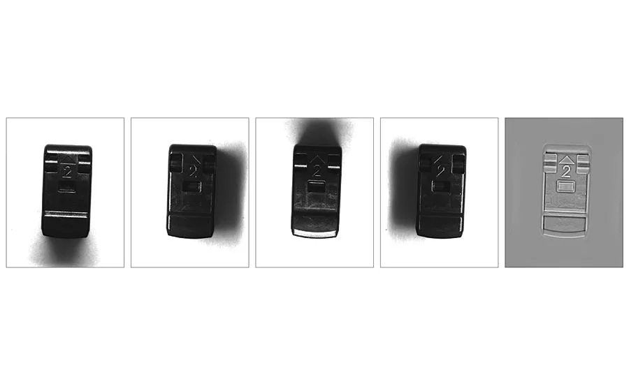
Figures 1-4. In these photos, the black plastic clip is illuminated from linear miniature (LM) LED lights positioned at 90-, 180-, 270-, and 360-degrees around the tire’s perimeter and controlled by an LED Light Manager (LLM). As the camera triggers each exposure, the LLM triggers a light from a different direction. The camera feeds each image into a PC running an image library photometric stereo registration algorithm, which takes the best pixels from each image and combines them into one composition (figure 5) that reveals more than any constituent images. Photos courtesy of Matrox Imaging
Real-world objects have depth, width and height, and automated systems such as robots need to “see” in these three dimensions if they are to operate successfully.
Machine vision systems composed of a camera attached to a computer running special image processing software give robots the “sight” they require. Ever since machine vision gained mainstream attention in the 1980s, however, one of the biggest challenges facing machine vision system designers has been how to best reduce the amount of data that needs to be processed to correctly locate, inspect and analyze an object.
Data reduction meant that machine vision designers tried to find ways to employ lights, filters and cameras to solve color machine vision applications using black-and-white cameras. The resulting grayscale images contain less data, making them easier to process quickly. Similarly, engineers would develop mechanical fixtures, motion control systems and other methods to solve a traditionally 3D application—such as guiding a robot to pick an object from a moving conveyor—with a 2D machine vision solution. This 2D solution might have used mechanical fixtures, for example, to guarantee that “non-flat” objects were always presented the same way, eliminating the need for accurate height information for every pixel, in addition to width and depth location coordinates.
Today, microprocessors, graphic processor units (GPUs), field programmable gate arrays (FPGAs) and other computational engines give designers the luxury of more processing power—but processing power isn’t infinite as a quick review of modern 3D machine vision methods reveals.
A Glance at 3D Vision
While the most challenging modern machine vision solutions that use technologies such as deep learning are being solved in the cloud, cost-effective processing power has relaxed the need for data reduction for the likes of color and 3D applications. For example, cheap data processing, lasers and optics have facilitated integrated laser triangulation systems for conveyor-based 3D systems that can generate tens of thousands of 2D profiles per second as a step toward creating a 3D object map. Other laser triangulation systems use galvanometers to quickly project a moving grid on stationary objects, resulting in high-resolution 3D surface maps. Conversely, new time of flight (ToF) cameras also offer low-resolution 3D maps for many applications without the safety concerns of laser illumination.
For larger-area 3D projects, designers have several options. Single-camera photogrammetric systems mounted on the end of a robot are one example. These systems take multiple pictures of the same object from different locations and calculate the 3D position of every pixel in the image based on a predetermined geometric relationship between camera and object. In the case of large-area 3D inspections, developers can simultaneously align two cameras next to each other like human eyes to capture 3D information based on minute differences between two images of the same object caused by perspective shifts between the two cameras—again using the known relationship between the cameras instead of the camera and object.
But for high-speed inspection of objects where the field of view isn’t large, quantitative 3D data isn’t always required for measurement purposes, whereas qualitative 3D data can be very useful by itself. An emerging machine vision technique called photometric stereo can be the most cost-effective solution in these types of applications.
Photometric Stereo: Localized 3D
While photogrammetric systems return quantitative 3D data based on known geometric relationships, photometric stereo isn’t primarily concerned with measuring the height of any given pixel. Rather, the technique uses 3D surface orientation and its effect on reflected light to produce—among other possibilities—a contrast image accentuating local 3D surface variations, which are potentially invisible with traditional 2D imaging. Photometric stereo solutions do not need to know the exact 3D relationship between the camera and the object under test, nor do they require two cameras to capture 3D data.
Instead, photometric stereo systems use a single camera with multiple sources of illumination. The photometric stereo technique for machine vision estimates the surface of an object by observing that object under different lighting conditions. This method is based on the fact that the amount of light reflected by a surface is dependent on the orientation of the surface in relation to the light source and the observer.
Photometric stereo for industrial applications is gaining attention thanks to new specialized algorithms, a growing awareness of the importance of good lighting to machine vision success, and low-cost multi-light solutions that allow the control of four or eight lights through a simple browser-based interface at less than the cost of a frame grabber or smart camera break-out box.
Today, the unique benefits of photometric stereo applications are enabling many common industrial inspection applications that once were difficult, if not impossible, to solve cost effectively.
Clips and Tires
For example, reading raised letters on parts has always been problematic for machine vision systems, regardless of whether the part is a truck tire or an automotive clip. In this example, a plastic connector has several functional features on its surface as well as the number “2” and a directional symbol. As you can see from the constituent images, there is no difference between material that comprises the clip and the raised letter, hence there is no contrast. On larger objects, such as tires, manufacturers have used laser triangulation systems to create a 3D surface map. Laser scanning systems for 3D measurements have become much more integrated and effective, but are still costly solutions, often requiring the object to be moving during inspection, adding to the cost and complexity of the automated solution.
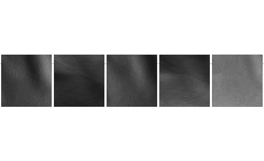
Figures 6-9. This set of four pictures shows synthetic leather material as illuminated individually from the four points of the compass. Visualizing 100% surface texture across the full image is nearly impossible for the human eye—much less a computer. The final composition from the photometric stereo registration algorithm (figure 10) shows an evenly illuminated texture across the camera’s full field of view with sharp contrast along each crevice and highlights perforations in the upper left quadrant. Photos courtesy of Matrox Imaging
In figures 1-4, the black plastic clip is illuminated from linear miniature (LM) LED lights positioned at 90-, 180-, 270-, and 360-degrees around the tires perimeter and controlled by an LED Light Manager (LLM). As the camera triggers each exposure, the LLM triggers a light from a different direction. The camera feeds each image into a PC running an image library photometric stereo registration algorithm, which combines all corresponding pixels to establish local surface properties—like curvature—and produce one or more types of composite images from these such as a contrast image of the local 3D geometries or an albedo image (figure 5). These composite images reveal more than any of the constituent images by themselves. The resulting composition clearly shows the edges that form the black-on-black lettering on the clips surface, as well as the edges of the various injection molded parts that make up the whole.
Perforations and indentations
The next example shows four more pictures of a synthetic leather material (figures 6-9). Like the organic material that it mimics, leatherette has considerable surface texture. Visualizing 100% surface texture across the full image is nearly impossible for the human eye—much less a computer.
In each constituent image, the warp of the material as it lies on a supporting substrate creates strong shadows while other parts of the image tend towards saturation due to strong light reflection. The final composition from the photometric stereo registration algorithm (figure 10) shows an evenly illuminated texture across the camera’s full field of view with sharp contrast along each crevice and the highlighting of holes. While organic materials like leather pose unique challenges for automated inspection systems due to constantly changing shapes and textures, the same can be said of pores on metal machined surfaces, such as engine heads, for example.
Outlook and challenges
Direct part marking (DPM) systems such as dot peen, laser marking and even cast parts are another area that will clearly benefit from cost effective photometric stereo solutions. Combining the examples above with the knowledge that we do not live in a 2D theoretical world, we can safely say there are more 3D applications than 2D (or 1D) applications. This explains why DBMR Research recently predicted that the global 3D machine vision market will grow at a CAGR of 9.5% between 2017 to 2024, increasing from $15.4 billion to nearly $32 billion in annual sales. The primary challenges to 3D machine vision market growth include the high costs of installation and lack of technical knowledge. As shown by a packaged photometric stereo registration tool and one-click programming of the LLM light management system, the machine vision industry is quickly overcoming cost concerns and technical difficulties. V&S
Looking for a reprint of this article?
From high-res PDFs to custom plaques, order your copy today!


