Empowering GD&T
Based on the ASME Y14.5 2009 Standard. Without GD&T, manufacturing is a guessing game.

GD&T is the only tool we have with which to manage machine part geometry perfectly. In particular, it’s the only tool we have with which to impose truly functional limits of imperfection on machine part features and actually guarantee assembly and operation prior to drawing release. GD&T is also the only tool we have with which to clearly communicate manufacturing objectives to the machine shop and with which to fully and functionally control coordinate metrology processes for manufacturing process assessment and refinement. Finally, the symbolic language of GD&T is also totally universal, does not depend on local languages and can be understood by engineers around the world.
The perfect imaginary world of GD&T is quite simple—it consists of only two things, 1) coordinate systems and 2) forests of tolerance zones which are oriented and located relative to them by basic dimensions. However, the symbolic language for specifying these items is unfortunately quite complex. And, as if its intrinsic complexity were not enough of a limiting force, the descriptions of its concepts, tools, rules and processes found in the two most important GD&T standards are often confusing and incomplete, namely in ISO 1101 and its numerous associated Standards, and in the ASME Y14.5 2009 Standard, which make it even more difficult to manage effectively. As a result, most of the GD&T “code” we find on models and drawings is dangerously “decorative” i.e. not function based, and rife with syntax errors, which users therefore have no alternative but to “interpret.” But if GD&T is open to interpretation, it is useless and must be abandoned.
And so, three questions arise: 1) how commonly is GD&T misused, 2) what are the costs of its misuse, and 3) what can be done to enable its proper use in order to make huge contributions to the bottom line?
It is hard to provide irrefutable estimates for the extent of the misuse of GD&T because of the complexity of the issues. However, based on years of experience on the part of the author and his colleagues, the percentage of improper and incomplete use of GD&T is surely on the order of 85 to 90%.
The costs of GD&T confusion, however, are easy to grasp and huge. They include a) the cost of the time required to clarify manufacturing and inspection objectives verbally, if machinists and inspection people dare express their concerns. b) The far greater cost of receiving non-functional parts or rejecting functional ones if those concerns fail to be expressed or addressed. c) The cost of switching to, or adding, new suppliers who bring new and different tribal understandings and confusion to the table. And finally, the cost of simply “giving up” on GD&T as too confusing and too costly to pursue, even if it is the only tool we have with which to manage machine part geometry perfectly.
In order to enable truly function based, syntactically correct, and fault tolerant “encoding” of GD&T, as well as totally unambiguous “decoding,” namely conversion of the code into reliable, truly functional manufacturing and coordinate metrology processes, the five fundamental components of GD&T, namely concepts, tools, rules, processes and best practices, must be utterly logically and clearly presented in the Standards that control them, and must be mastered and managed by dedicated corporate support teams. Said teams must be made responsible for providing real time guidance to their design, manufacturing and QA teams, must be required to take full responsibility for drawing release, and must provide regular internal training. In addition, and surely the most important tool we need, we must develop and supply an utterly smart, 3D model based, rule managed, GD&T Encoding & Decoding Engine to create syntactically correct, truly feature function based code and code assessment. Truly worthy GD&T code can only be efficiently and affordably generated, assessed and refined by an artificially intelligent system which we can only hope will appear soon, namely before GD&T is set aside as too complex to continue to struggle with.
Interim Means for Refining & Empowering GD&T
In the absence of truly capable, 3D model based, smart GD&T encoding and decoding engines, the only means for advancing the success of GD&T is to “clean up” the Standards. The current ISO and ASME GD&T standards are worthy of much respect, but are in many aspects 1) inadequately clear, 2) unnecessarily complex, and 3) missing the “rules” needed to enable logic based “encoding” and “decoding.” The remainder of this article is therefore an attempt 1) to clarify some of GD&T’s most important “concepts” and “tools” using concise terminology in place of the often confusing terminology found in current standards, 2) to refine and expand the rules with which to enable truly function based code, and 3) to provide insights into some of the “encoding” and “decoding” processes which enable logical and functional GD&T. This will be done with short overviews of such items in the following paragraphs, but enhanced by extensive additional information to be found at www.qualitymag.com which also includes references to the actual Y14.5 2009 Standard definitions.
Concepts
GD&T is brimming with important concepts like “Datum Features,” “Datums,” “Basic” dimensions and “Simultaneous Requirements,” to name just a few, which must be clearly understood in order to use the tools effectively. The following paragraphs present definitions of just two important concepts, namely Datum Features and Datums, with many more available in the online resource mentioned above. The emphasis in every case is on not only defining “what” we are dealing with, but making clear what purpose each item serves.
For refined definitions of the following additional concepts, please go to the “Concepts” entry in the online resource:
- Basic Dimensions
- Datum Features
- Datum Targets
- Datums
- Datum Feature Simulators
- Datum Reference Frames
- Tolerance Zones
- Tolerance Zone Mobility
- Virtual Maximum Material Boundaries
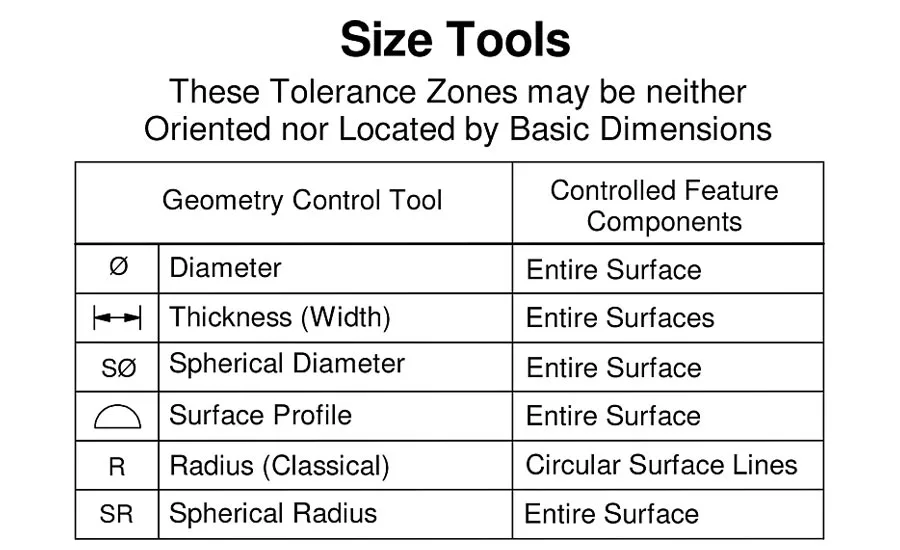
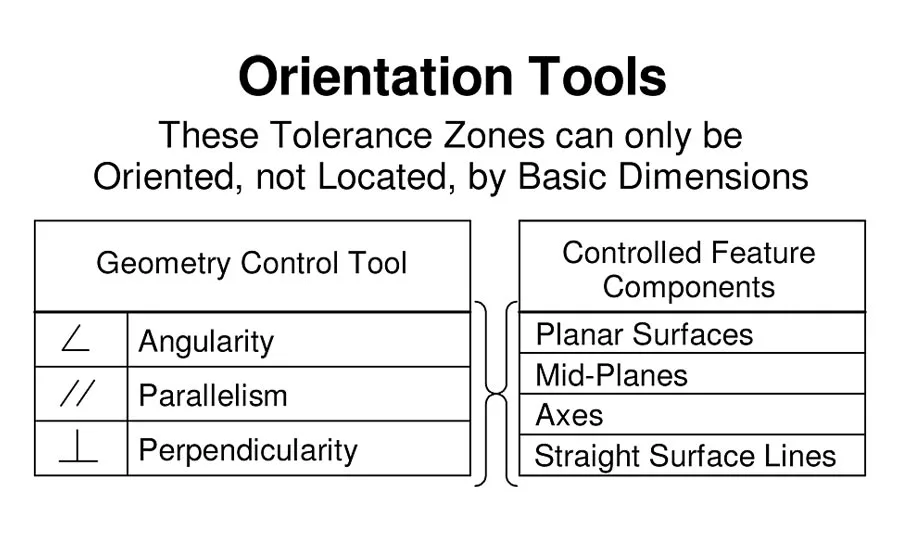
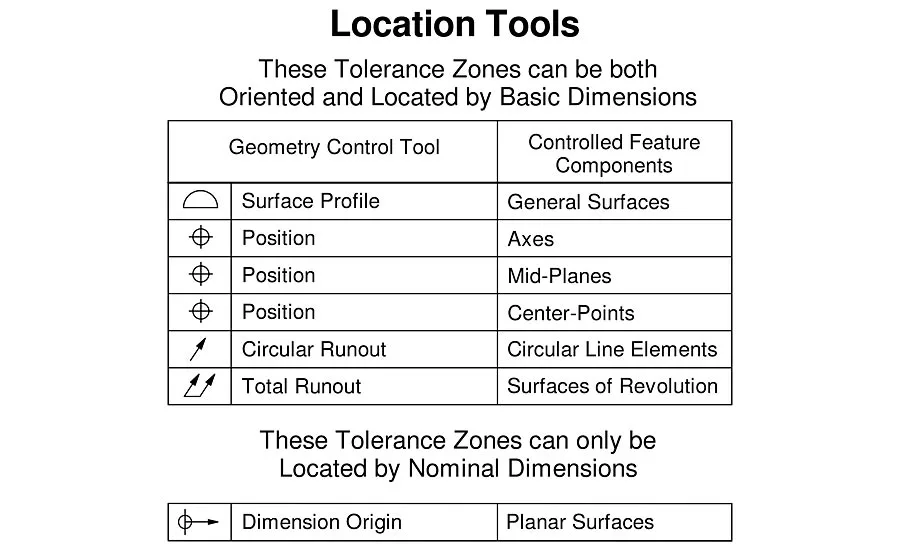
Geometry Control Tools
There are only four things that can go wrong with the geometry of machine parts: 1) size, 2) form (including finish), 3) orientation and 4) location. There are also four sets of “tools” with which to impose constraints on what can go wrong. The following charts list all the truly functional tools in the Y14.5 2009 set, and include their names, their symbols, and the feature components they control.
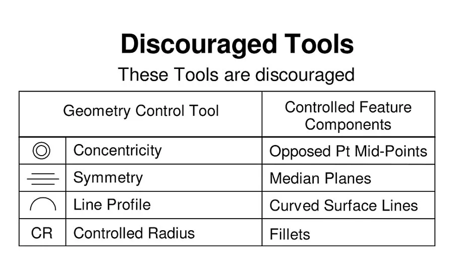
In addition to the tools referenced above, there are some of highly questionable value, whose use is “discouraged” based on explanations provided in the online resource:
Rules
If GD&T is to be of any use, it must encode the actual functional requirements which a feature must fulfill in terms of assembly and operation, and must be uniquely “decodable.” Given the complexity of its symbolic language and its many tools, the only way to achieve “worthy GD&T code” is with the help of rules. The Y14.5 2009 Standard presents an extensive collection of rules in §1.4 (p.7), and many others in various other sections. Please go to the “Rules” entry in the online resource to review the following ones:
- The Envelope Rule
- Rules of Datum Reference Frame Establishment
- Rules of Datum Feature Simulator Management
- Rules of Simultaneous Requirements
- Rules of Composite Feature Control Frames
- Rule of Material Condition Modifier (S)(M)(L) Applicability
- Rule of Material Boundary Modifier (S)(M)(L) Applicability
- Rule of Feature Control Frame Stacking (Proposed)
Processes
GD&T includes many processes, for example Datum Feature Selection, Datum Feature Sequencing, Geometry Control Tool Selection, Tolerance Zone Modifier Selection, Feature Control Frame Stuffing, Virtual Maximum (and Least) Material Boundary Determination, Tolerance Stack Up Analysis, Feature Control Frame Decoding and Datum Reference Frame Establishment, to name a few. For insights into some of these, please go to the “Processes” entry in the online resource.
- “Datum Feature Selection”
- “Datum Feature Sequencing”
- “Geometry Control Tool Selection”
- “Material Condition Modifier Selection”
- “Material Boundary Modifier Selection”
- “Feature Control Frame Stuffing”
- “Virtual Maximum Material Boundary Determination”
- ”Feature Control Frame Decoding”
- “Datum Reference Frame Establishment”
Best Practices
No tools or processes are universal. Each has its specific strengths and weaknesses under certain circumstances. A small number of best practices are therefore addressed in this section of the online resource.
- Controlling the Size of Cylindrical and Spherical Features
- Explicit Datum Reference Frame Axis Labeling
- Ordinate Dimensioning
- Breaking the Symmetry of Symmetric Parts
- Constraint Requirements for Non-Rigid Parts - Sheet Metal, Rubber & Plastic
- Threaded Feature Management
Conclusions
Again, GD&T is the only tool we have with which to manage imperfect geometry perfectly. However, if its sets of concepts, tools and rules are incomplete or confusing, they stand in the way of our success. If we can improve them to better enable GD&T, it is our duty to do so! Readers wishing to submit comments are strongly encouraged to do so at www.qualitymag.com. We thank you.
For an expanded look at GD&T, read more with our GD&T resource guide.
Looking for a reprint of this article?
From high-res PDFs to custom plaques, order your copy today!


