Metrotomography Brings New Precision to CT
While CT may have been niche technology in the past, today it is helping manufacturers all over the world solve difficult R&D, quality and production problems.
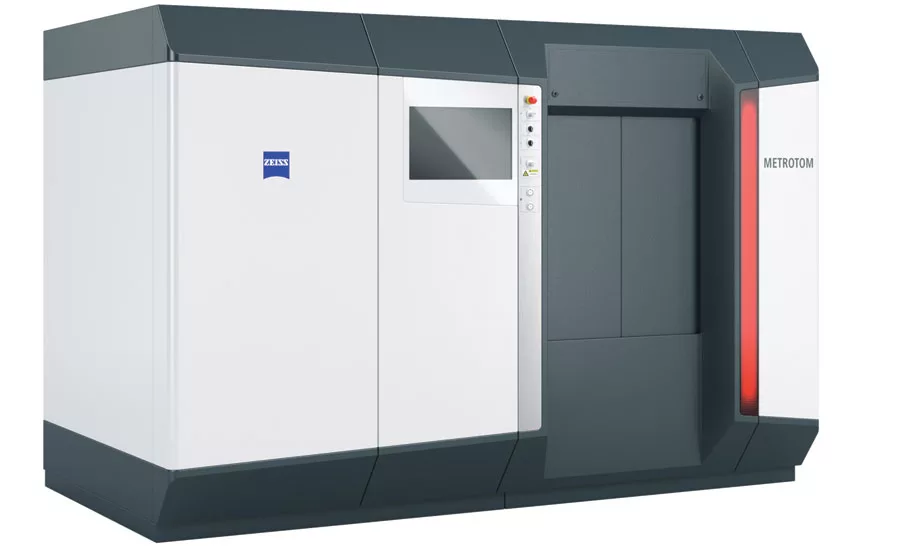
The METROTOM is an industrial computer tomograph for measuring and inspecting complete components made of plastic or light metal. Source: Zeiss
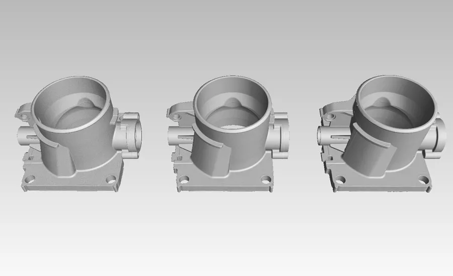
This is the same part scanned at three different speeds. They all appear the same until you have the software compare them. Source: Zeiss
Color used to show dimensional variation to the baseline part. Fig1: Part Scanned 30% faster than baseline. Fig2: Part Scanned 100% faster than baseline. Source: Zeiss
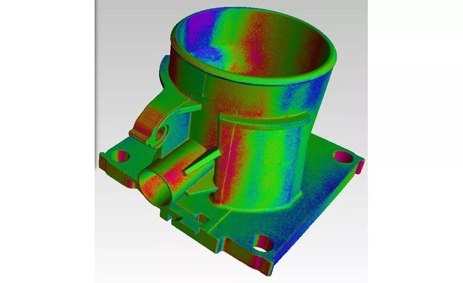
Color used to show dimensional variation to the baseline part. Fig1: Part Scanned 30% faster than baseline. Fig2: Part Scanned 100% faster than baseline. Source: Zeiss
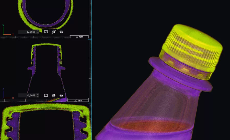
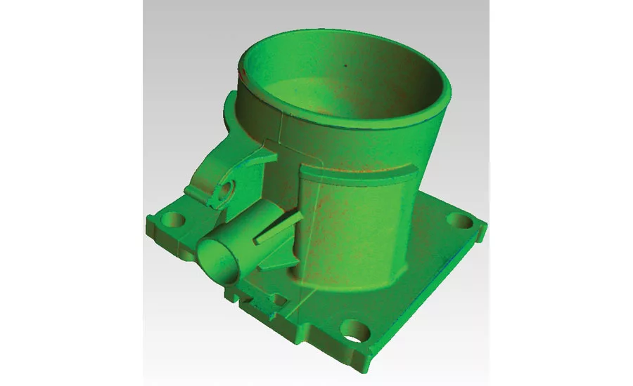
The software uses color to show different parts (densities) of the assembly. Color transparency is added to accentuate details further. Source: Zeiss
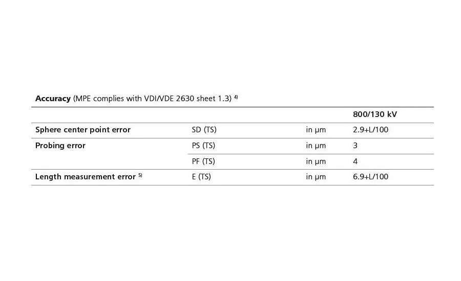
Look for these MPE (x) values on the spec sheet.
Modern manufacturing demands more precision than ever in both individual parts and assemblies. Computed tomography (CT) is a potentially valuable tool for ensuring that precision. In much the same way that a CAT scan produces a 3D image of the body, a computer assembles a series of two dimensional X-ray images taken of a rotated object. Software then joins them to produce a 3D representation.
CT has traditionally been used for nondestructive testing (NDT) to find internal flaws in parts without having to perform “surgery,” but meeting today’s needs requires better hardware, software and controller technology than has traditionally been used for industrial CT.
Range of Industries
Traditional CT has been used to simply find the presence of flaws. It was never designed to closely measure their dimensions, so hardware and software were designed or repurposed to meet that requirement. And it was never intended to measure external characteristics. That is still an acceptable standard for some applications, but in today’s environment there are many applications in which more accurate measurement is needed. These include R&D, product design and prototyping, quality engineering, various aspects of manufacturing, and product recall management in fields including medical device, plastics, connectors, 3D printing, tooling, automotive, and aerospace.
In all of these cases, a suitably equipped CT system can provide actual measurement of dimensions both inside and outside an object or of parts within an assembled package. To do that the technology has to make the transition from “pass/fail” to actual measurement. This new approach applies the techniques of metrology to the process of tomography and is called “metrotomography.”
High-Value Applications
Forensic evaluation is a major application for CT, one in which accurate measurement is critical. For example airbag issues have been in the news lately. These were caused by problems within the assembly that could not be identified except by viewing the device as a whole. In this and other applications, even parts that individually meet spec can deform, impinge, or interact in other unintended ways when assembled. For that reason disassembly is not a viable option for troubleshooting.
Plastic manufacturing is another application that can benefit from metrotomography. If injection molded or blow molded parts were perfect images of their molds, mold design would be a simple matter of replicating the original CAD model. But, in fact, hot plastics can shrink, sink, or warp as they cool. These are changes that must be compensated for in the design of the mold. The traditional way to verify a mold design is to make a mold, produce a part, measure that part. With that information, designers can then remake the mold or change machine settings to correct the problem. The traditional process of measuring test pieces can involve multiple pieces of measurement equipment. It’s an iterative, trial-and-error process that relies to an extent on individual expertise and intuition, and that can take days or weeks for each iteration.
While this approach can be effective, it takes too much time and manpower to be effective in today’s fast-moving world. Remaking a mold is expensive and time-consuming, and while parts are being analyzed, the mold (and potentially an entire production line) may be sitting idle. Anything that speeds up the process or reduces the number of iterations can help slash development costs and move products to market for quicker return on investment.
Return on Investment
Metrotomography makes parts measurement more of a science, providing hard data that can be fed back into the mold making process. In the same way, metrotomography can simplify verification of tooling for machining processes and can be used for accurate verification of 3D printing processes. They can be used on a variety of materials. And because metrotomography systems accurately measure both internal and external features, they can replace separate CT and metrology systems. This can reduce both equipment cost and “real estate” requirements. Effective metrotomography systems can fully examine a complex metal part in minutes and a plastic part in seconds, making it an ideal technology when 100% inspection is required. But many factors affect a CT system’s accuracy, ease of use, and throughput including hardware design and software capabilities.
Hardware Factors
One aspect of hardware design that can affect a system’s accuracy is the amount of adjustability built into the system. While flexibility can seem like a benefit, every additional degree of freedom—the ability to move the X-ray source or X-ray detector—is a potential source of error. A system that can meet your needs with fewer adjustments is likely to be more accurate. And while CT requires that the part be rotated, the rotary table is another potential source of inaccuracy. Since it is fundamental to accurate positioning of a part during inspection, the platform’s bearing technology has a significant impact on results.
Unless a system is working in laboratory conditions, temperature in the environment can change, and that too can impact measurements as system components expand or contract, reducing the repeatability of measurements and leading to “drift.” In an NDT application for which many CT systems were originally designed, that may not make a difference, but when the goal is accurate measurement, small differences add up. A well designed system controls the impact of temperature on the equipment.
Compensating for Hardware Inaccuracies
While inherent accuracy is best, there are a number of ways in which systems try to compensate for “drift.” One is to regularly recalibrate the system. There are two problems with recalibration as a solution to drift. One is that it takes time and manpower, shutting down measurement operations and potentially the processes it serves. The other problem is that between recalibrations, measurements become increasingly unreliable, raising the question of how much inaccuracy you can tolerate before taking the system temporarily out of service.
Another alternative is “scaling,” comparing a part being analyzed to an item of known dimensions and using an algorithm to compensate for error. It has limited usefulness because X-rays scatter as different wavelengths encounter and edge; as a result error rates at different scales are non-linear.
Finally, you can tighten standards for acceptance of parts. This eliminates acceptance of sub-standard parts but can lead to scrapping parts that would pass if accurately measured. Reducing yield in this way can be costly. These problems can be avoided by using a system that by-design ensures accurate measurements of parts.
Data Accuracy (Dimensional Correctness)
Would you buy a measuring instrument (caliper, height gage, CMM, etc.) if the manufacturer did not certify its accuracy? As previously noted there are two distinct classes of CT scanners: Traditional CT scanners and CT-CMM scanners (Metrotomography systems).
- Traditional CT Scanners: These are designed to nondestructively visualize internal defects of parts or assemblies. While the same data can also be used to generate measurement results like distance, angle, diameter, etc., the numbers aren’t to be trusted. Currently there is only one recognized specification for manufacturers to state their CT accuracy: VDI-VDE 2630 1. Traditional CT Scanners do not state accuracy per VDI-VDE.
- CT-CMM Scanners: These are purposely designed to perform like a coordinate measuring machine. The best ones have a well-considered temperature management system including a kinematic design that resists unwanted structural stress and yields data repeatability. Their guideways and rotary axis performance is typically measured with a laser interferometer so that static and dynamic deviations can be corrected by the controller while scanning. As a final step in their production process, the accuracy performance of these systems must meet their VDI-VDE specifications.
Summary: Most manufacturers offer both CT types. Each will produce stunningly photo realistic images but only VDI-VDE specified units should be trusted for dimensional reporting.
Speed / Throughput
There are no free rides in the world of CT. Like a car, the scanning speed (throughput) of any CT machine can be increased, but at what cost? With a part in hand, inquire what the scan time would be to have a high degree of confidence in the results. Next, scan a part and use the results as your baseline. If you plan to report dimensions (length, width, diameter, etc.) inquire if their system’s MPE(x) accuracy statements are guaranteed (qualified) at that speed. With baseline data in hand you are better prepared to compare throughput tradeoffs like accuracy and image sharpness.
Software Factors
If a CT machine is going to be used like a CMM it should utilize certified CMM software. The problem is that not all CMM software can directly support CT datasets. If CT data has to be converted for use by the software, the conversion will add uncertainty to the results. This is particularly true of software originally designed for white light or laser scanning and requiring that the part data is converted from its natural state (CT Voxel format) into a more compact stereo lithography (STL) format before processing.
Mixed materials can be a challenge for CT machines. If you plan to measure parts or assemblies that use a mix of materials, ensure the software incorporates algorithms to accurately measure each, compensating for the difference in their relative densities. Other factors in evaluating CT/CMM software include ease of setup and programming and clarity of reporting and presentation of results.
Choosing a CT System Vendor
A specification sheet is a good place to start but the most valuable way to judge a system is via a live demonstration, ideally in a setting similar to yours and on your own parts. Get your part(s) on the scanner as soon as you arrive and keep the scanner running all day. Watch the setup process and examine the system output and report flexibility. Have the manufacturer prove that the system can repeat its measurements over the course of a day. Ask where the OEM’s CT support labs are located, as well as how many CT application engineers and service engineers are on staff to support your facility. Armed with that information you should be able to choose the best system for your needs.
Choosing a CT Service Provider
A little extra research beyond service provider websites and tradeshow booths will help strengthen your trust. See the facility and meet the operators. Ask what quality certifications the operators have: PE, CQE, GDT-P, ASME Level I, etc. Ask where they received their CT training and experience. What was the latest training course they attended? What’s their protocol to peer review customer data? Look for records showing the CT system(s) are regularly maintained by the manufacturer. Be extra cautious if the services provider uses a homemade2 CT scanner. Why take the risk when there are plenty of service providers using recognized CT scanners? Ask where your parts will be scanned and where the data will be analyzed. Some companies may outsource inspection and analysis without your knowledge.
A good way to build a solid CT purchase justification is to have a service bureau handle your CT scanning needs (for a period of time) using a system from the manufacturer you may someday purchase from. And even better, working with a CT manufacturer’s in-house service lab allows you to gain trust in their abilities and form a lasting relationship that could extend into your CT ownership.
Summary
While CT may have been niche technology in the past, it has moved way past the early adopter stage and is today helping manufacturers all over the world solve difficult R&D, quality and production problems. The future is brighter than it has been for CT-CMMs—expect to start seeing much more information about this exciting technology. j
1 B89.4.23: While not formalized, a B89 subcommittee is working on a CT performance specification similar to the VDI-VDE 2630.
2 The knowledge to build a crude CT scanner can be sourced from the Internet. Caveat Emptor
Looking for a reprint of this article?
From high-res PDFs to custom plaques, order your copy today!


