LED Lighting Tackles High-Speed Imaging Challenges
Understanding the proper choice of lighting is critical when vision systems must operate at high-speed.
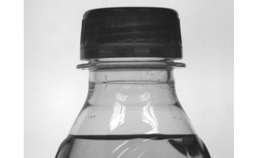
Figure 1: The magnitude of the image pixel blur depends on the rate of speed of the moving part and the camera’s field of view and response time. Source: Smart Vision Lights
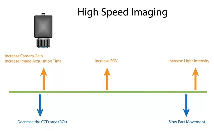
Decreasing the speed of the moving part and/or windowing the ROI of the camera may not be an option for developers of machine vision systems. While increasing the acquisition time and the field of view of the camera can be used, these too may limit performance. Increasing the intensity of light then remains the best option. Source: Smart Vision Lights
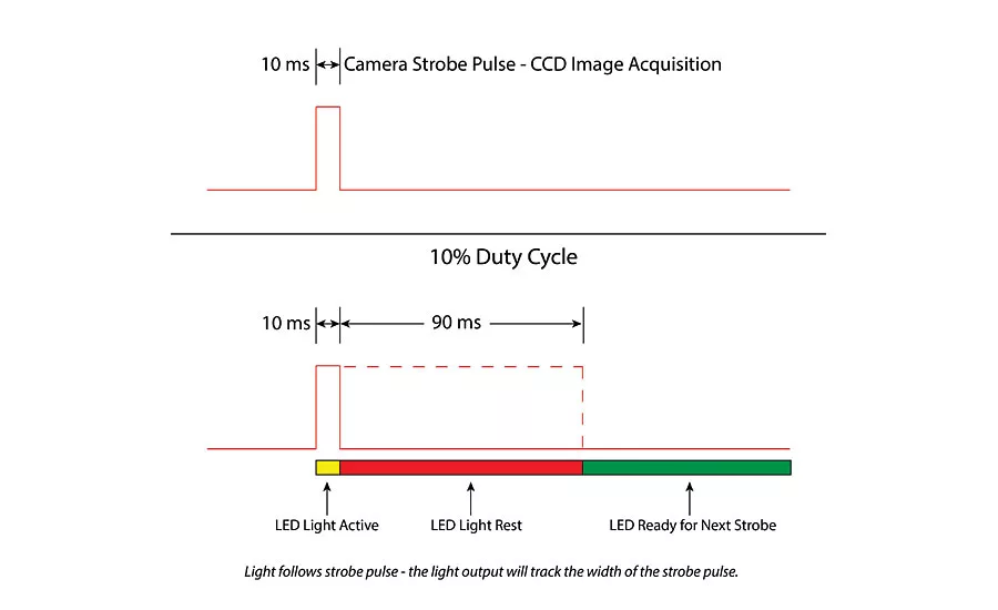
When used in strobed mode, the duty cycle is determined as the ratio between the strobe time and rest time of the LED. Source: Smart Vision Lights
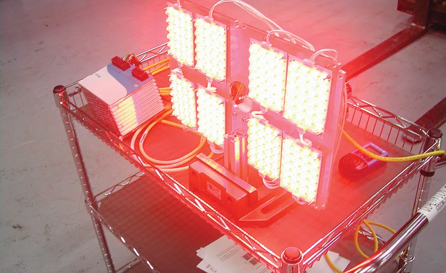
A custom LED application for high-speed face recognition demanded a high-powered light positioned 25ft from a vehicle. When strobing, 2000W was used but the average 50W of power reduced the heat dissipated allowing the enclosure to be positioned on the side of a highway without requiring cooling. Source: Smart Vision Lights
Lighting
With the introduction of CMOS-based image sensors, camera manufacturers have introduced products with ever increasing frame rates. These include standalone cameras for scientific, ballistics and R&D applications and lower cost cameras with high-speed camera-to-computer interfaces targeted at machine vision applications. While standalone cameras may include on-board processors and memory and are relatively expensive, their less expensive counterparts may only feature rudimentary camera control functions, offloading memory buffering functions to the host computer.
One feature both types of camera have in common, however, is the ability to use region of interest (ROI) windowing techniques to increase the speed of image capture. Previously, when high-speed images were captured by a camera, the camera shutter was synchronized with the strobe. Today, since CCD and CMOS-based cameras incorporate electronic shutters, constant illumination sources can be used instead. However, in constant operation, the illumination source is an inefficient system, since it may only be required to be active for 1% of the time while the camera exposes an image.
Reducing blur
When capturing images at high-speed it is important to reduce the amount of pixel blur that may occur. Pixel blur is dependent on the speed of the moving part, the size of the field of view (FOV), the number of pixels in the image sensor (image size) and the exposure time of the camera. To calculate the pixel blur as it relates to line speed, exposure time, the image size and the field of view (FOV), the following formula can be used:
Blur in Pixels = (Line speed* Exposure time)*(Image size/FOV)
Using this equation, the exposure time for a specific pixel blur can be calculated. For example, for a pixel blur of 1 pixel, a line speed of 100mm/s, an image size of 640 x 480 and an FOV of 150mm, the exposure time will be 2.3ms. A pixel blur technical note, found on http://smartvisionlights.com, can be used to calculate pixel blur. (The technical note can be found at http://bit.ly/2kpuWZC.)
Different techniques can be used to capture images at high-speed. These include increasing the FOV of the camera, widening the aperture of the lens and/or increasing camera gain. Of course, each of these has its drawbacks. Increasing the FOV of the camera, for example, will result in a decrease in the resolution of objects within the image. Decreasing the size of the captured image using ROI techniques will again affect the obtainable resolution for a given FOV. And, while widening the aperture of the camera will result in more light being captured by the camera’s imager, the result will be a smaller depth of field being imaged. Increasing camera gain boosts the apparent brightness of an image at a given exposure but at the same time amplifies the noise within the image.
Increasing light
One of the most effective ways to reduce the exposure time of the camera is to increase the amount of light used to illuminate a scene. To decrease the exposure time needed to capture images at high speed, it is advisable to use a bright light operating in a strobed mode. In machine vision applications, Xenon or pulsed LED light sources can be used. In the past, Xenon strobe lights were commonplace. Such Xenon flash lamps require high voltage sources to discharge energy into the lamp but, because of these high voltages, discharge flash lamps can misfire. LEDs, on the other hand, are semiconductor devices driven by low voltages, making them more reliable and capable of running consistently for millions of flashes.
While the light pulse from a Xenon strobe source can last from 250ns to as much as 8ms, 15-30ms pulse durations are common. Although they produce a large amount of light for the time they are active, Xenon flash lamp bulbs have a short maximum strobe time commonly less than 100Hz or 100 strobes/s.
For the time the Xenon light is on, therefore, 12/(1/100,000) or 1.2Million Lumens of light will be produced. To replace this high intensity flash light with an LED light is challenging. To attain the same luminous output as a Xenon flash strobed for 10µs would require hundreds of LEDs—more than is practical.
Many machine vision applications, of course, do not require 10µs flash durations and, for those systems that can perform in the 50-300µs range, LEDs can outperform Xenon strobes. If an LED light is strobed for hundreds of microseconds, for example, it can produce more light intensity than a Xenon flash lamp and even more when the LED is strobed for milliseconds. With faster strobe durations of hundreds or thousands of strobes/s, high-power LED lights can outperform their Xenon counterparts in applications where very fast (10µs) pulses are not required. Indeed, some machine vision LED lights can strobe at rates beyond 5kHz although rates above this diminish the advantages of overdriving.
Unlike single wavelength LEDs, Xenon light sources emit wavelengths from the ultraviolet (UV) to the infrared (IR) spectrum between 185nm and 2000nm. In this respect, the spectral output is similar to sunlight making them suitable for microscope applications and solar simulators. Of course, using multiple LEDs of different wavelengths can be used to simulate this broad spectrum. However, in many machine vision applications, such a broad spectral output can be disadvantageous since the wavelength of light used in any application can be an important variable in the inspection process. When a part is illuminated by light of a particular frequency or color, for example, contrasting colors will appear darker in the image, making image processing tasks easier. While the lifetime of Xenon light sources is between 2,000 and 3,000 hours, the lifetime of LEDs is far longer. According to LED vendor Cree, for example, under normal operating conditions LEDs can be expected to last as long as 50,000 hours.
Strobing LEDs
LED vendors expect their customers to use their devices in constant operation at a low current. Because of this, they do not discuss using the devices in strobed mode, relegating the task to the developers of machine vision illumination systems. Over driving an LED involves pulsing the device at very high currents for a short time and then allowing a rest time. To do so, many manufacturers have developed strobe controllers that can drive LED lights with currents of 10A or 20A, but there is a point of diminishing return where increasing this current by a specific amount will not increase light output by that same amount. Light output may even decrease as the internal temperature of the LED increases.
As a rule, we strobe our high-power LED lamps at 4x the rated current. Of course, such strobing limits the duty cycle of the LED light. One series of lights includes an integrated strobe driver that feature a 10% duty cycle, such that when the light is strobed for 1ms, the LED is turned off for 100ms before the next strobe is activated. This is usually fine because the time taken to capture and process the image and perform the I/O functions required by the machine vision system all need to occur before the light is again activated.
One example of how effective LEDs can be in high-speed imaging applications is that of a tracking system required to perform face recognition. This application demanded a high-powered light positioned 25ft from a vehicle and a vision system to perform face recognition. To do so required strobing the light—a process that consumed 2000W. However, the average 50W of power needed reduced the heat dissipated allowing the illumination system’s enclosure to be positioned on the side of a highway without requiring cooling.
Looking for a reprint of this article?
From high-res PDFs to custom plaques, order your copy today!


