Closed Loop Manufacturing: CAD Driven Supplier Quality
CAD simulation benefits both OEMs and suppliers, and incorporating supplier measurement data gives powerful tools for quality improvement.
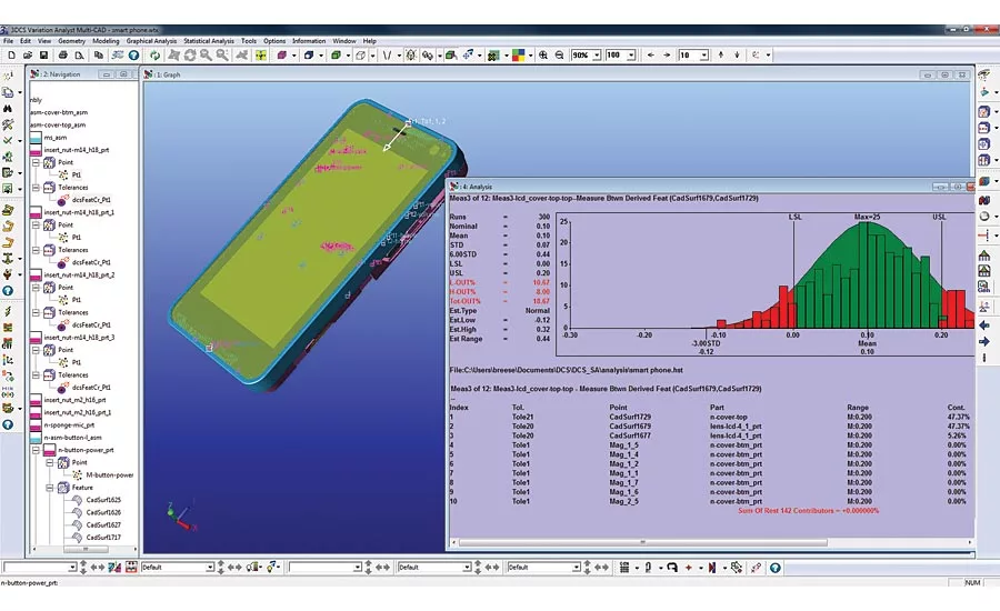
3DCS Variation Analyst, a dimensional simulation tool for tolerance analysis, can be used to validate GD&T and assembly in order to reduce scrap and rework during production.
CAD simulation has become a standard at OEMs and large manufacturers. Conducting tolerance analysis, finite element analysis and other forms of simulation optimize designs and improve manufacturability. These simulations, when combined with correlated inspection, create feedback loops that manufacturing engineers can use to find root cause production issues, account for mean shifts, validate tooling and assembly changes and promote continuous process improvement.
What is Closed Loop Manufacturing?
Closed loop manufacturing is a closed loop process of manufacturing and inspection (measuring). The key element to a closed loop process is inspection in manufacturing. By feeding the inspection data upstream in the process, designs can be continuously improved. The goal is to reduce quality costs like scrap and rework while improving the quality and accuracy of the produced parts.
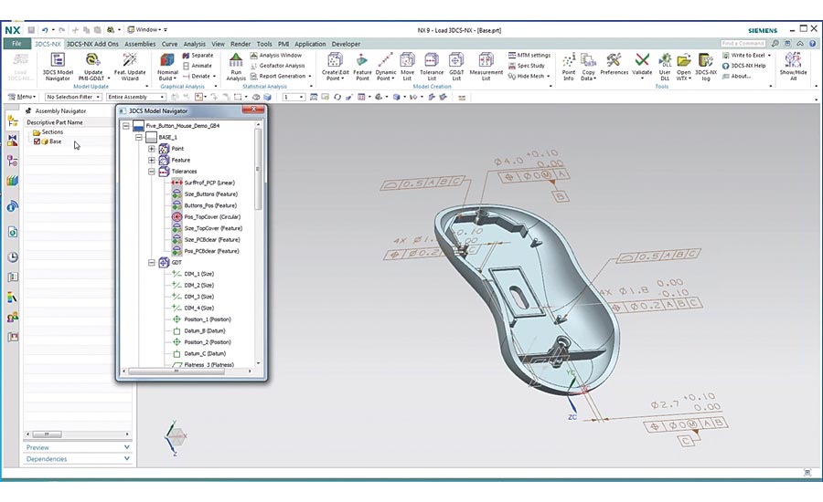
In order for CAD to drive the manufacturing process, the OEM needs to be utilizing simulation to validate GD&T and assembly processes. This is a form of Design for Manufacture and Assembly (DFMA) connected to Model Based Definition, whereby the CAD model becomes the sole source of information, GD&T and drawings and is used in simulation to pre-determine production issues and the viability of production. This process does not have to be fully implemented, but in order for a Closed Loop Process to exist, there must first be a process for using and applying CAD simulation. This works best when simulation is being conducted at both the OEM and the supplier, but can work when only the OEM is using simulation. There are a variety of reasons both OEMs and suppliers would utilize simulation, and they are not always for the same purposes.
The Value of Simulation at the OEM
Simulation provides the OEM with a variety of benefits. For example, tolerance analysis is a method of simulating the dimensional variation of parts as they are incorporated into an assembly and combine, or stack up, to create a compounding effect that shifts parts and components out of alignment. Dimensional variation in production is a given, because, as of yet, there are no viable production processes that can be used to create perfectly shaped parts. Simulating the tolerance stack up gives engineers the ability to design with this variation in mind, producing designs that contain features to control the variation, such as larger openings and gaps to make room for variation or processes and tooling to reduce the variation.
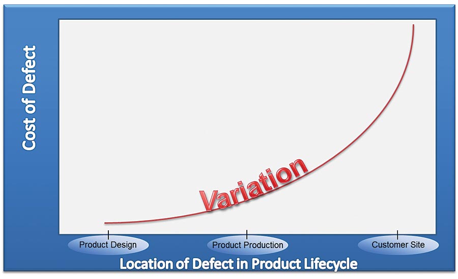
The cost of making changes and finding defects becomes exponentially higher the later they are found in the product lifecycle.
Determining the effect of variation early using simulation gives manufacturers the time to make design changes, as well as keep the costs of those changes small. When negative effects of variation are found later in the product life cycle, they become much more costly to fix. These fixes often require many parts to be reworked or replaced, and if found late enough, can end up causing recalls and large warranty claims. There is great value, then, in finding as many possible production issues as early as possible, and determining critical to quality points where possible problems may occur.
Simulation gives suppliers the evidence-based information they need to negotiate tolerances and specifications with their customers.
The Value of Simulation at the Supplier
Suppliers also gain great value from simulation. If the supplier is a Tier 1 or a large supplier, they may design and manufacture parts and gain the same benefits as an OEM from simulation. Many suppliers are contract manufacturers and produce parts from a design given to them by an OEM or higher tier supplier. You might think that simulation is unnecessary for a manufacturer who is given the design to build to, and should only be concerned with meeting the given specifications of the product. This is not the case, as simulation gives suppliers valuable insight into the product they are manufacturing, and more so, provides factual evidence to support negotiations with their customers.
Many designs incorporate general tolerances. These are design specifications for the amount of allowable variation on a given part. When a general tolerance, which is a generic tolerance setting, is applied it often fails to account for features that do not require exacting specifications, thereby wasting time and money on overly accurate parts, and at the same time, fails to account for critical components that may require more exacting specifications, thereby requiring additional rework and fixing before final assembly or delivery. A supplier can use tolerance analysis simulation to determine which areas are critical, and may require more expensive processes, and which areas are not, allowing for less expensive processes, and then use this information to support discussions with the OEM and their customers to get design concessions. Having simulation results as proof can often mean the difference in these kinds of negotiations, and can account for large savings for both parties.
Problems with Data Correlation in the Supply Chain
As many manufacturers have learned, what the OEM is measuring, and what their suppliers are measuring are rarely the same thing. Furthermore, many suppliers give measurement results in a blindingly large amount of formats, which makes it difficult to understand and use the results to determine if the parts are good or bad.
When using CAD simulation, this adds another layer of difficulty. In order to incorporate the supplier information into a CAD model for analysis, the measurements need to align with the CAD points, so that an accurate depiction of the part can be simulated. Communicating this information can be a real challenge in itself, even when the supplier is provided the CAD model.
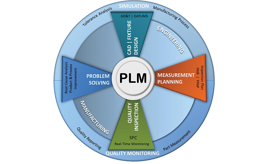
Closed loop manufacturing connects engineering and manufacturing while providing feedback loops of information to continuously improve both design and process.
Applying a Closed Loop Process to Supplier Quality with the Industrial Internet of Things (IIot)
The Industrial Internet of Things (IIoT) is the application of the Internet of Things (IoT) to manufacturing. The key idea to the IIoT is the creating of a network of devices and computers that collect and share information. This is completed by aggregating data into a single database, either on the Cloud or at a local site, and then sharing that information with users in a manner that promotes effective decision making.
CAD integrated analysis tools provide inspection labs with correlated measurement plans to standardize their measurement program.
Closed Loop Manufacturing can take advantage of the IIoT in CAD and inspection plans to correlate the data for easy use in root cause analysis, correlation studies and continuous improvement. This process begins with simulation, creates measurement plans for coordinate measurement machines (CMMs) and inspection devices from the CAD model, and provides those to suppliers, who then measure to those plans and return the data into a central database to be mined for metrics and information.
This process can be automated with systems to improve communication and give visibility into the supply chain. These statistical process control (SPC) systems connect suppliers and OEMs, automating the delivery of inspection plans and collection of measurement data, constantly updating the OEM with quality metrics and information about the supplier parts. Suppliers in turn can use the inspection plans and SPC system to understand what their customers are looking for, and manufacture to those metrics and specifications. This empowers suppliers to view and improve quality on their end before sending parts and data to their customer, who gain visibility into the quality of the parts before they arrive.
Methods to Correlate CAD and Measurement Data
As mentioned previously, IIoT gives manufacturers new tools to correlate CAD and measurement data. These often take the form of software systems that allow automated exchanges of information between OEMs and suppliers. Simulation provides the answer to the question: where do I measure? and the system creates the communication channel to collaborate with suppliers across the world. Let’s discuss an example of what this would look like in practice.
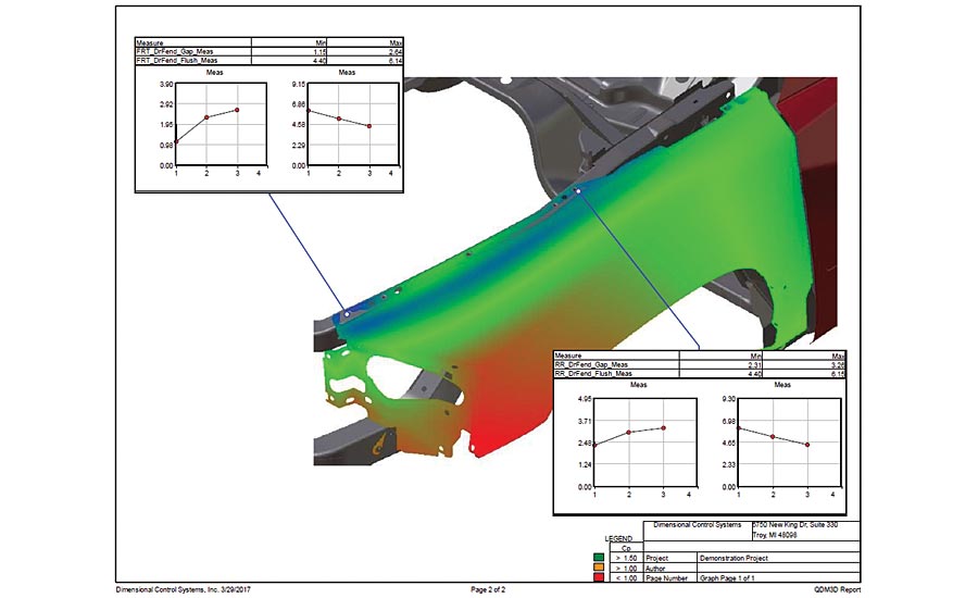
Using CAD generated measurement plans allow manufacturing engineers to correlate measurement data to provide immediate context for quality and compliance reports.
Example Use Case
Let’s take the case of a global OEM and its supply chain. This OEM is headquartered in the United States with suppliers in China, India, Brazil, Austria and Mexico. The goal is to implement a global measurement plan for quality improvement and supplier quality assurance.
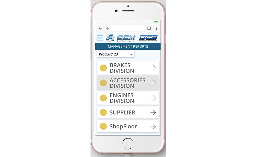
Using a centralized SPC system allows companies to mine the information in real time and provide up-to-the-minute updates on quality across the production environment.
This takes the form of two deliverables:
Dashboards of individual suppliers at four levels of production to monitor quality through specific metrics, in this case, PP and PPK.
CAD models that incorporate both simulated data and measurement data, so that they can be used to promote design optimization early in production, and then used for root cause analysis during production.
Body in White (BIW) Correlation
To obtain these two outputs, a Closed Loop Process is incorporated. This process is completed through the following steps:
Assess the design intent results from the CAD simulation tool
Analyze the SPC results from measurements
Derive the optimal body model
Feedback the analysis results from the model to improve design intent
Assess the Design Intent Results from the CAD Simulation Tool
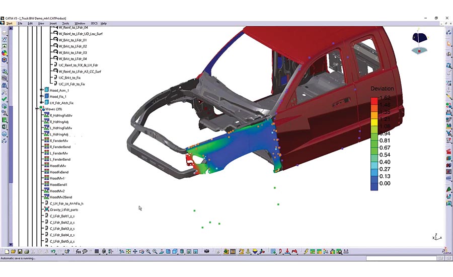
The OEM begins with Monte Carlo simulations using the CAD model incorporating the design inputs; tolerances and assembly process. This determines optimal GD&T and the points that are critical to quality. These points are output as a CMM plan and uploaded to the SPC system to be downloaded by suppliers and fed into their CMMs.
Analyze the SPC Results from Measurements
Data from the CMMs is uploaded into the SPC system, which houses it in a central database and analyzes it, delivering PP and PPK to key decision makers as a dashboard, and to manufacturing engineers and quality managers as reports utilizing the CAD model for context. This data is used by manufacturing engineers in the CAD model, rerunning the Monte Carlo simulations to validate the results and make improvements to the design process.
Derive the Optimal Body Model
The improvements are incorporated into the CAD model, along with determinations by managers based on quality feedback, which creates an Optimal CAD Body Model.
Feedback the Analysis Results from the Model to Improve Design Intent
The CAD model is used to create drawings and make determinations in assembly process and tolerance application (GD&T) to further improve the production process, and fed upstream to improve the original design.
Summary
Applying simulation and a closed loop manufacturing process are not small feats, but when properly utilized can provide powerful benefits by reducing the costs associated with quality. Through a connected quality system, CAD data can be harvested to drive planning and production, and utilized in feedback loops for effective continuous improvement. These factors together can be used by manufacturers to produce better products at lower costs.
Looking for a reprint of this article?
From high-res PDFs to custom plaques, order your copy today!


