Getting the Best Out of Bore Gages
Data collection capability, careful selection and use are key.
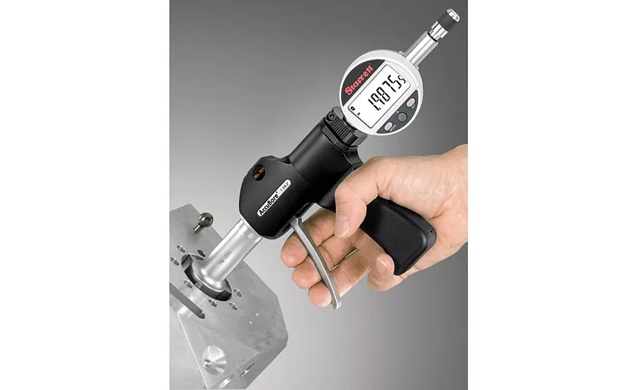
This electronic bore gage offers Bluetooth capability.
For the most productive and efficient bore gage measuring solutions, it is beneficial to take some time to examine technology options. Choosing the right gage for your application will ultimately save tens of thousands of dollars and lead to increased accuracy. To begin the selection process, it is useful to review how you collect and record measurement data.
Machinists, inspectors and engineers use bore gages to check inside diameters of holes, cylinders and pipes. Dimensional part data are usually never collected. When collected, the data are often manually collected and entered into a Microsoft Excel .csv or .xls file so that basic tolerances can be controlled within a large lot quantity of parts, or documentation can be produced in the event of a commercial discrepancy.
With manual inspection data collection, the repetitive hand movements required to pick up tools, measure parts, put tools down and then record results is time consuming. Furthermore, hand writing or keying in data is error prone, resulting in scrap, excess inventory and even rejected parts.
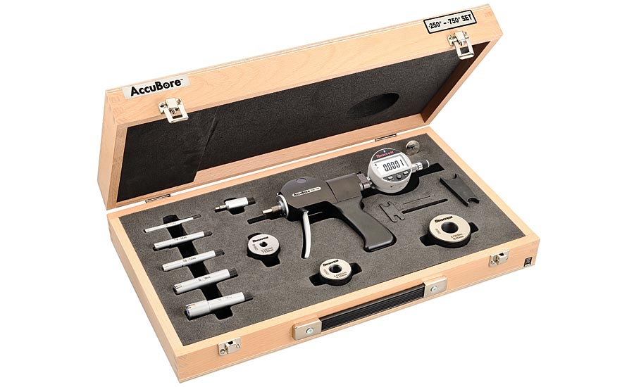
This electronic bore gage set include gage, contacts, setting rings, instructions, certificate of calibration and a 3v battery in a protective carrying case.
When collecting manually, the data may be fragmented and only given to a single individual (or just a few individuals). Although the data goes where it needs to go to make an improvement, execute the changes needed, or report findings to management, the data trail may end there with no opportunity to use it again. Capturing the data to uncover more efficiency is lost.
In the best case scenario, a feedback model is in place and shop data are reported to a quality team or other areas of the shop. The data could range from low coolant levels, broken/ bad tooling, machine troubleshooting, supplier material changes, customer demands, etc.
Also, collecting data manually is not the most efficient way to keep track of a maintenance program which tracks calibration dates and overall gage management system statistics. Relying on randomly documented information to create data histories would be challenging to use as a consistent resource.
This electronic bore gage provides IP67 level of protection as well as Bluetooth capability.
Considered a level above manual data collection, collecting the data via a wired cable connected to an electronic gage can be a useful option. However, there are even more productive solutions where wireless technologies in tools such as a bore gage transmit the measurement data wirelessly to another device. Looking ahead to Industry 4.0 initiatives, it will be increasingly important to instantly share consistent, accurate data throughout an organization.
Five tips for examining your data collection process
- Determine what you are collecting now.
- Determine how you are collecting now.
- Identify the “Big 3” problems your operation is experiencing (for example, incoming material issues, print-to-build discrepancies, machine breakdowns, tooling expenses, areas where bad parts are a continuous issue).
- What dimensional metrology measuring gages are you currently using?
- What dimensional metrology tools/gages could you upgrade to electronic tools capable of data output?
Wireless Benefits
When it comes to measuring holes, especially when there are a large quantity of holes, Bluetooth enabled bore gages can easily and wirelessly collect this data. The technology enables users to measure and collect error-free data to output for statistical process control (SPC) analysis and much more. Issues with data cables are eliminated including placement, installation, safety and high cost, and gages can easily be brought to the hole.
In addition to data collection methods, there are other important considerations when selecting a bore gage solution.
Prevent Out-of-Roundness
When machining bores, challenges with fit and out-of-roundness may result in lobing. Out-of-roundness can be caused by centerless grinding (5-lobing), a worn or out-of-balance spindle (irregular-lobing), workholding with a three jaw chuck (3-lobing), and other sources. In an internal roundness scenario, lobing often occurs when applied forces on a limited wall thickness surpass the material’s yield limits. The result impacts the roundness of the internal diameter.
Conversely, external roundness can be impacted when machining a material where its strength is inconsistent through the workpiece (coatings, for example). Out-of-roundness can be uncovered by irregular travel of an indicator or parts not fitting properly. Out-of-roundness is either asymmetrical (irregular lobing) or symmetrical (regular lobing). Empirically discovering that the fit is incorrect can be too late and very costly to rework.
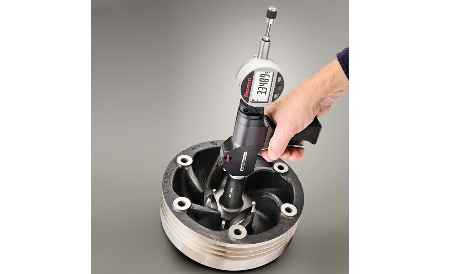
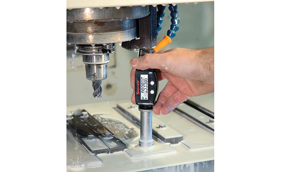
Electronic bore gages have a high-quality, trigger-activated, two and three-point contact gaging system with extended range.
Selecting the most appropriate bore gage will significantly minimize these challenges. Sometimes, roundness geometries are important enough to have metrology equipment specially designed to measure it. This is a costly, but very effective way to profile the specific roundness of a part. If the parameters can be established for the finished part, specific operations can then be monitored in-line with a bore gage. This can reduce the expertise required, empower operators, and improve the end results of the finished parts.
Roundness or ovality (a basic subset of roundness) is typically not specified, however. But understanding the character of an internal diameter can build confidence when qualifying your work. An effective internal diameter requirement with an overall tolerance is more typical. Bore gages can improve confidence as opposed to using a slide caliper or other two-point instrument. The benefits include greater resolution, accessibility to depth, and ease-of-use.
Selection Tips
Whether to use a two-point or three-point contact measuring tool is an important decision since there are some differences. A two-point contact rod-type inside micrometer is usually lighter, easier to handle and more versatile over long ranges from approximately six to 107 inches (150 mm – 2,700 mm). Compared to a three-point contact any two-point contact micrometer, regardless of range, can probe a hole better to find the geometry of that hole.
Most three-point contact tools have setting rings to ensure accuracy. If the goal is very close tolerance work with two-point contact inside micrometers, it is recommended that they be set to a ring gage or to an outside micrometer.
A three-point contact micrometer has an advantage in that it can be seated in position more quickly than a two-point contact tool. The three-point tool will tell the maximum true diameter that can enter the hole a little faster than a two-point contact tool. The measuring heads used in these tools are accurate to ±.0001 inch or 0.002 mm, but overall accuracy on all measurement equipment is dependent on good practice and technique.
Best Practices When Using Bore Gages
To ensure accuracy, these practices should be followed when using a bore gage:
- Always make sure that there are no specks of dirt between the clamping surfaces of the rods and micrometer heads
- Tighten all rods uniformly and consistently, not too tight or too loose, but a fairly firm assembly
- Assembling long sections should be done vertically or with support, horizontally
- Because temperature can affect long rods used in these tools, they should be assembled in the same environment in which they will be used
Following these tips for selection and use, combined with optimal data collection will give you the best bore gage solution. Whenever in doubt, consult with the bore gage manufacturer for recommendations and technical know-how.
Looking for a reprint of this article?
From high-res PDFs to custom plaques, order your copy today!


