Alternating Current Field Measurement Testing
A number of industries use ACFM to inspect welded connections for surface-breaking defects.

Figure 1. Uniform field under the sensor area
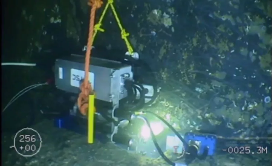
Figure 10. Remote ACFM deployment example
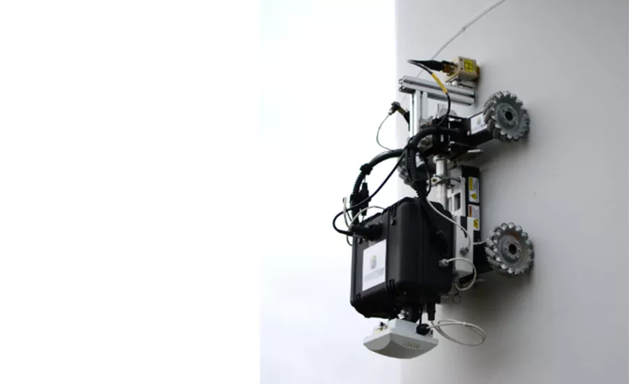
Figure 10. Remote ACFM deployment example
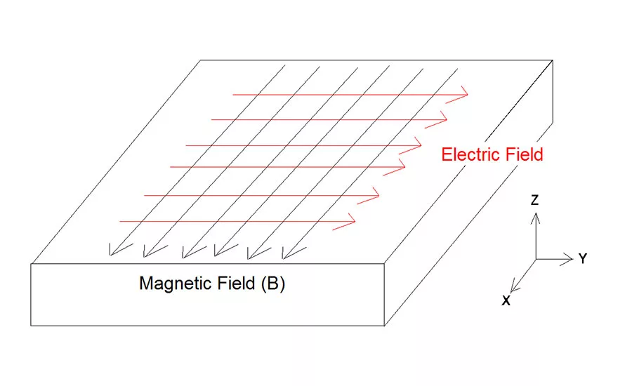
Figure 2. ACFM coordinate system
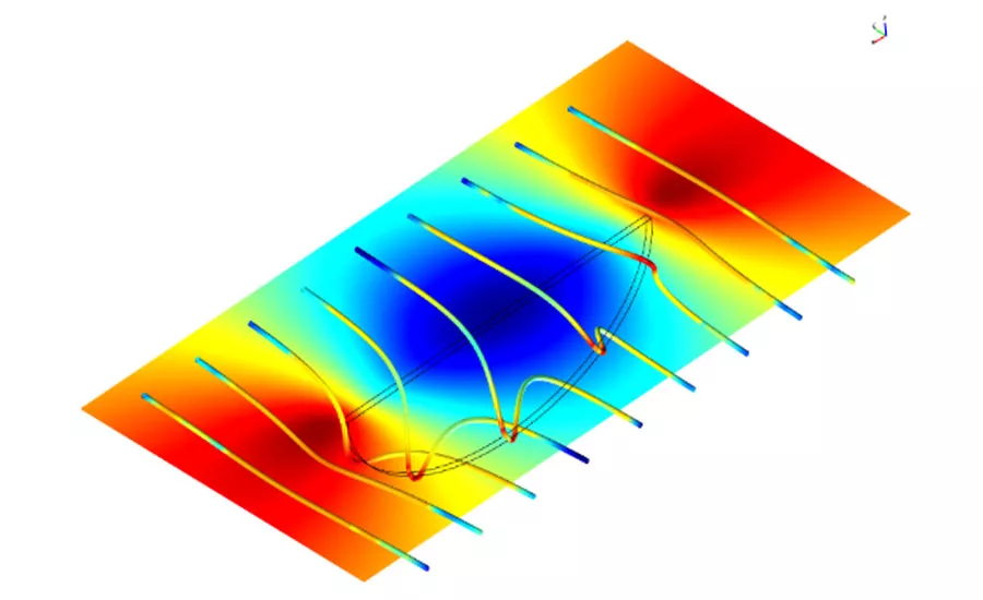
Figure 3. Disturbed electric field around a linear defect and effect on Bx strength
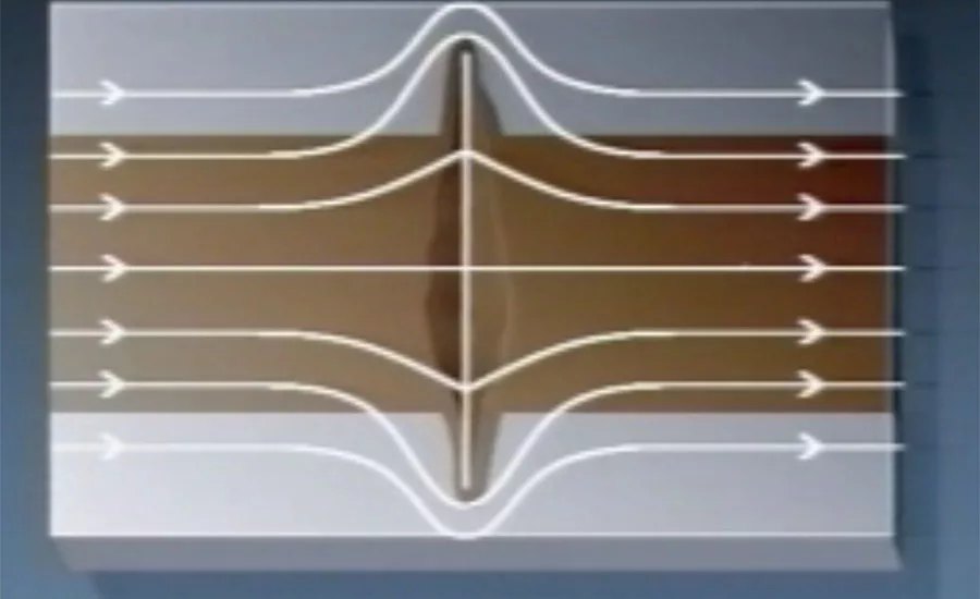
Figure 4. Rotation of current around ends of defect and effect on Bz
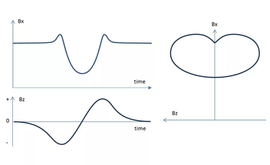
Figure 5. The butterfly plot from a defect produced from the Bx and Bz traces
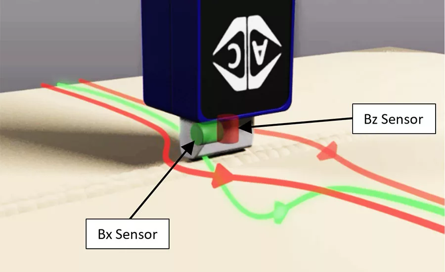
Figure 6. Sensor orientations
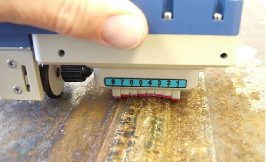
Figure 7. Examples of compliant and custom profiles
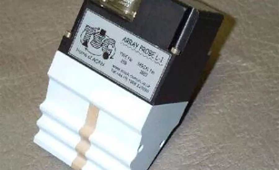
Figure 7. Examples of compliant and custom profiles
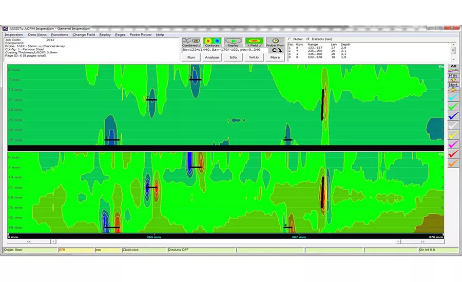
Figure 8. ACFM array Bx and Bz data C-scan display
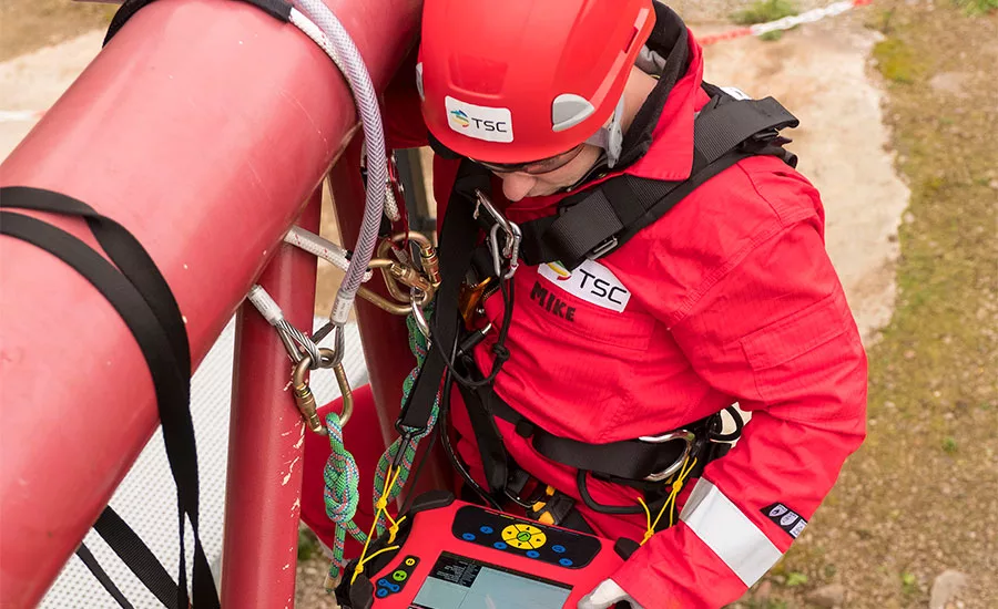
Figure 9. Rope-access inspection with ACFM
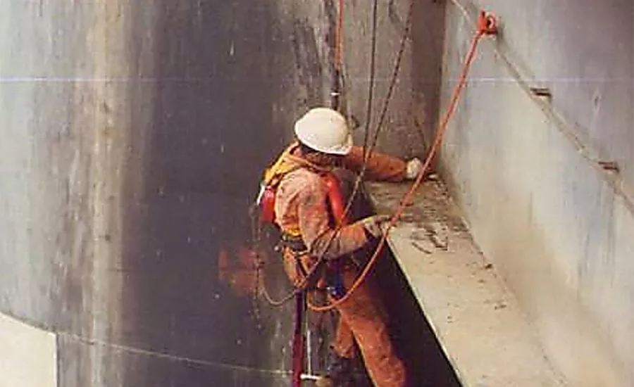
Figure 9. Rope-access inspection with ACFM
First, a little history. The alternating current field measurement (ACFM) nondestructive testing technique was developed in the ‘80s to detect and estimate penetration depth of fatigue cracks in underwater welded tubular intersections of offshore oil platforms. Prior to the advent of ACFM, these defects were generally detected and their length measured with magnetic particle inspection.
The severity of fatigue cracks (directly related to the remaining life of structures) is commensurate with how deep they are. At the time, conventional eddy current testing systems were not well suited for use underwater or for welds in ferritic steel. They were unable to accurately measure defects deeper than 5 mm (0.2 in). Alternating current potential drop (ACPD) was the technique used to measure depth, but it was slow and very difficult to use underwater because of the need to maintain very good electrical contact between the voltage probe and the steel surface.
Addressing this problem required a noncontact equivalent to ACPD. A group of United Kingdom oil companies approached the University College London to develop the new technique: ACFM.
Operating Principles
ACFM locally induces a uniform current into the component under test and measures the density of the magnetic flux over the component surface. The electric field is typically induced at a frequency of 5 kHz which, on carbon steel, results in the currents being confined to a thin skin at the material’s surface. Surface-breaking defects perturb the induced current, thus the magnetic flux density. ACFM measures two components of the magnetic flux density: one offers information about the position of defect ends (ergo the defect’s length). The second component provides the aspect ratio (and hence depth) of the defect. The components combined to confirm defect presence and, with a sizing algorithm developed from theoretical models, establish surface length and depth.
The primary direction of induced currents is designated as the Y axis, while the direction of the associated magnetic field in and immediately over the surface is designated as the X axis (as shown in Figure 2).
When the component under test is devoid of defects, the current flows along the Y axis and the magnetic field along the X axis. The magnetic field’s Y and Z components (designated By and Bz) are zero, while the X component (Bx) is proportional to the magnitude of the electric current.
Fields Around Defects
When a linear surface-breaking defect is present in the component under test along the X axis, cutting across the electric current lines, the current is forced to flow around and under the defect’s ends.
As it flows under the defect, some of the current is forced away from the surface. This reduces the strength of the magnetic field in the middle of the defect (blue in Figure 3). Some of the current flows around the ends of the defect, strengthening the magnetic field at the ends (red in Figure 3). As it does, a partly circular flow appears. This rotation around the ends of the crack produces a measurable, non-zero Bz.
Butterfly Plot
ACFM produces a third trace, referred to as a butterfly plot. It is composed of the Bx and Bz sensor data, plotted against each other. The Bx amplitude is plotted on the vertical axis and the Bz amplitude is plotted on the horizontal axis. (See Figure 5.)
The resulting display removes the time element from the scan, removing scan speed variation effects.
Pros and Cons of ACFM
ACFM has several advantages and, of course, disadvantages.
The main advantages of ACFM include:
- Test through coatings as thick as 5 mm (0.2 inch)
- Measure the depth of surface-breaking cracks as deep as 25 mm (1 inch)
- Easy to test material boundaries (e.g., welds) because they are parallel to scan paths
- No on-site calibration necessary
ACFM has the following disadvantages:
- On smooth, clean surfaces, ACFM is generally less sensitive to short/shallow defects than conventional eddy current testing.
- Geometry changes such as edges and corners can produce confusing signals
- The sizing model is based on linear fatigue cracks—other forms of defects can lower sizing accuracy.
Anatomy of ACFM Equipment
The basic ACFM probe contains a minimum of three elements:
- Magnetic field inducer
- Magnetic sensor to measure flux density along the X axis
- Magnetic sensor to measure flux density along the Z axis
Basic ACFM probes can only inspect a narrow strip 10–15 mm (0.4–0.6 inch) wide, centered on the probe sensors.
Array ACFM Probes
To inspect wider areas in one pass, array ACFM probes are engineered to contain several sensor pairs adjacent to each other. The sensor array profile can have multiple configurations.
Some array probes feature a Y-field inducer perpendicular to the primary, X-field inducer, and an additional By sensor, making them capable of inspecting in two orthogonal directions simultaneously to detect and size defects in any direction.
Array data can be displayed as traditional trace plots or as C-scans, where red peaks and blue troughs appear against a green background level (See Figure 8).
Typical ACFM Applications
A number of industries use ACFM to inspect welded connections for surface-breaking defects. Because array ACFM probes offer a wide coverage and relative tolerance to liftoff, they can be part of remotely deployed solutions, such as scanners and crawlers. Applications where this is useful are where direct human access is difficult, unsafe, or costly.
Non-Ferromagnetic Materials
ACFM is usually used on ferromagnetic materials, where it achieves the highest sensitivity. However, it’s also been used on non-ferromagnetic materials such as austenitic stainless steel (nuclear storage tank pools), titanium (offshore risers), and Inconel (threaded connections on down-hole motors) with great success.
Acceptance and Standards
Weld Inspection
ACFM is widely accepted by major organizations in the oil and gas, petrochemical, and marine industries, as well as others. Approval takes various forms, sometimes issued asset owners, insurance companies, or certification bodies.
In the oil and gas industry, a number of the certification authorities approved ACFM to inspect offshore installations in above water and subsea applications. Several recommended practice and procedure documents include ACFM.
Thread Inspection
ACFM is also the accepted MPI alternative when inspecting drill string threads in the North Sea and recommended practices were issued.
References
- ABS, Guide for Nondestructive Inspection of Hull Welds, 2018. ww2.eagle.org/content/dam/eagle/rules-and-guides/current/survey_and_inspection/14_ndi_hullwelds/NDI_Guide_e-Feb18.pdf
- ASTM, Standard Practice for Examination of Welds using the Alternating Current Field Measurement Technique (E2261-03), latest revision: E2261-17. www.astm.org/Standards/E2261.htm
- ASME V Article 15, Alternating Current Field Measurement Technique (ACFMT), 2006. www.asme.org/products/codes-standards/bpvcv-2017-bpvc-section-vnondestructive
- North Sea standard NS-2 (1999), latest revision 2012. www.fearnleyprocter.com/ns-2-standard
Looking for a reprint of this article?
From high-res PDFs to custom plaques, order your copy today!


