How to Create an AS9102 First Article Inspection Report
Despite the name, the inspected article may not necessarily be the “first” produced, but a sample from the first production run provided to the customer.

First article inspection (FAI) is a process to validate your manufacturing process can produce an item that meets the requirements as designed. In the aerospace and defense industries in the U.S. most companies are conducting AS9102 first article inspections. Other industries also use inspections to validate their manufacturing processes, but they vary from company to company with the format and when in the production process they are completed.
AS9102 is the SAE requirement (written by the International Aerospace Quality Group, IAQG) that governs first articles in the Americas. The AS9102 standard defines first article inspection as, “A planned, complete, independent, and documented inspection and verification process to ensure that prescribed production processes have produced an item conforming to engineering drawings, DPD, planning, purchase order, engineering specifications, and/or other applicable design documents. (Ref 9102 Rev B, Sec 3.10.) The first article inspection report, “The forms and package of documentation for a part number, sub-assembly, or assembly, including associated FAI results, as defined by this standard.” (Ref 9102 Rev B, Sec 3.11.)
When to conduct a First Article Inspection
A first article inspection is typically called for in a purchase order contract between the producer and buyer. All designs should be completed before a FAI is conducted. Once the design is finalized and production processes have been determined, a FAI can be performed on the first production run. A FAI should be repeated whenever there is a change in design that affects the form, fit, or function of the product.
Despite the name, the inspected article may not necessarily be the 'first' produced, but a sample from the first production run provided to the customer. Typically this is one part, but some customers may require more.
When to conduct a first article inspection:
- On the first production run.
- If there is a design change.
- If materials or source changes.
- If it has been 2+ years since the last production run.
- If there is a change in process, tool, or location.
Parts of an AS9102 FAIR
The first article inspection report (FAIR) consists of three forms:
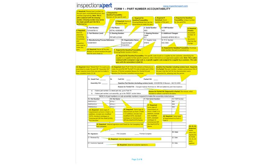
Form 1: Part Number Accountability - Used to identify the product that is having the first article inspection conducted on detail part, subassembly, or assembly. Also known as the “FAI part.”
Form 2: Product Accountability – All material and process specifications, as well as any special processes and functional testing defined as design requirements, must be accounted for on form 2.
Form 3: Characteristic Accountability, Verification and Compatibility Evaluation - All product characteristics such as dimensions, tolerances, notes, etc. must be accounted for on form 3. An inspection drawing or model is required where all inspection characteristics are clearly identified with uniquely numbered inspection balloons. Often referred to as a “ballooned” or “bubbled” drawing. The numbers on the inspection balloons must correspond to the characteristic numbers on form 3.
Conducting your First Article Inspection
When conducting your first article inspection and creating your FAIR you can use the tools you already have in your shop. With Microsoft Excel, and Adobe Acrobat or Microsoft PowerPoint, you can create all the documentation you need for your FAIR. However, there are purpose-built software options that can make the process of first article inspection more efficient. We’ll cover several options for each step of the first article inspection.
Step 1: Create Your Inspection Plan
For characteristic identification put uniquely numbered balloons next to each inspection characteristic on the drawing. There are several ways to do this:
Manually: Print a paper copy of your part drawing and identify features you are required to inspect. Draw circle (balloon/bubble) next to each characteristic and write a unique identifying number inside each circle. A stencil can be used to ensure circles are uniform.
Digitally: Open a digital copy of your part drawing in Adobe Acrobat, MS PowerPoint, or similar software. Using the shape tools create a circle next to each feature. Type unique identifying numbers inside each circle.
With Inspection Software: Open your part drawing in your inspection planning software. Select each feature that you need to inspect and the software will place a balloon and a unique ID number in one step.
Next, create a table of the requirements to be inspected, the table should include the balloon number, spec, and tolerances from your part drawing. This table will be filled out with the inspection results for form 3 after the part has been produced.
Digitally: Retype all inspection characteristics into an Excel file, including dimensions, geometric tolerances, characteristic number (AKA the balloon number), reference location, and unit of measure.
With Inspection Software: Most inspection planning software on the market uses optical character recognition (OCR) to extract all of the feature information (nominal, tolerance, USL, LSL, etc.) while you balloon. This means that your table of characteristics will already be done by the time you’re finished ballooning your part drawing.
Step 2: Manufacture the Part
Build the product and ensure you are documenting processing and inspection results for the requirements during production.
Step 3: Inspect the Part & Collect Inspection Results
How you collect your inspection results will depend on the tools you use to inspect. If you’re using analog gages you will type inspection results into your characteristic table (form 3 of your AS9102 FAIR). If you’re using a CMM or bluetooth digital gages you have more options.
Digital (non bluetooth) and Analog Gages: As you inspect the part type your inspection results directly into your FAIR, or if you’re using FAI software you may be able to type results into the software.
Bluetooth Digital Gage: Many of these allow you to push a button and send the measurement result into a specific cell in your spreadsheet. This will require that you have a computer at your inspection station.
CMM: Most CMMs will produce a text based document with your dimensional results. Depending on how your data is formatted you can copy and paste this data into your inspection report. Avoid retyping printed CMM data into a FAIR. It’s time consuming and error-prone. Depending on the FAI software you may also be able to import CMM data directly into your inspection plan and create an inspection report from your FAI software.
Step 4: Create your First Article Inspection Report
Forms 1 and 2 require objective evidence be provided to confirm materials, special processes, and/or functional testing meet the requirements specified by the customer. (AS9102 Sec 4.5 (b,c,& d)) This evidence is usually in the form of certificates of conformance from suppliers, material test reports, etc. Ensure you that you have completed these forms and attached required documentation.
Considering purchasing software for FAIRs?
Pros of using software for creating your inspection reports:
- Time - using software to balloon and extract in one step is much faster than either drawing them on your printed paper part drawing or using Adobe to draw balloons on your PDF part drawing.
- Accuracy - the less typing that’s required in a process, the more likely you’ll be able to improve the accuracy of your inspection report. Even if the software isn’t perfect in recognizing your inspection characteristics, instead of spending your time typing, you’re spending your time double checking the software output.
When evaluating software for conducting first article inspections, here’s what you should consider:
- What types of drawing files do you usually get from your customers, and does this software handle those file types? If you get mostly scanned PDFs and the software will only balloon text-readable PDFs then it’s not going to be able to balloon and extract most of your drawings. Or if you get a lot of CAD models from your customers, you need to make sure that your FAI software can balloon CAD drawings.
- How many first article inspections do you conduct? Can the software help produce other types of reports your company or customers require? The frequency and the complexity of the first article inspections you conduct, along with other inspection reporting requirements, will determine whether you need an inspection planning software.
If you’re spending any measurable amount of time manually conducting FAIs then it makes sense to evaluate a software solution. NDT
Important Definitions
Design Characteristics - Dimensional, visual, functional, mechanical, and material features or properties, which describe and constitute the design of the article, as specified by drawing or DPD requirements. These characteristics can be measured, inspected, tested, or verified to determine conformance to the design requirements. Dimensional features include in-process locating features (e.g., target-machined or forged/cast dimensions on forgings and castings, weld/braze joint preparation necessary for acceptance of finished joint). Material features or properties may include processing variables and sequences, which are specified by the drawing or DPD (e.g., heat treat temperature, fluorescent penetrant class, ultrasonic scans, sequence of welding and heat treat). These provide assurance of intended characteristics that could not be otherwise defined. (Ref 9102 Rev B, Sec 3.6)
Designed Tooling - Product specific tooling [e.g., check fixtures, coordinate measuring machine (CMM) program] specifically made to validate the design characteristics of a product. (Ref 9102 Rev B, Sec 3.7)
Digital Product Definition - Requirements of any digital data files that disclose, directly or by reference, the physical or functional requirements, including data files that disclose the design or acceptance criteria of a product. Examples of DPD include the following:
- The digital definition and fully dimensioned two-dimensional (2D) drawing sheets.
- Three-dimensional (3D) data model and simplified or reduced content 2D drawing sheets.
- The 3D model with design characteristics displayed as text.
- Any other data files that define a product in its entirety. (Ref 9102 Rev B, Sec 3.8)
Drawing Requirements - Requirements of the drawing and associated parts lists, specification, or purchasing document to which the product is to be produced from, including any notes, specifications, and lower-level drawings invoked. (Ref 9102 Rev B, Sec 3.9)
Looking for a reprint of this article?
From high-res PDFs to custom plaques, order your copy today!


