Easing the Inspection Task
Recent developments in various NDE modalities are making inspection more accurate and faster while providing data that is easier to interpret.
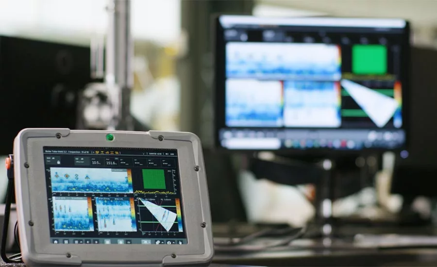
Fig 3. HD Images Provided by Mentor Visual iQ
As nondestructive examination (NDE) continues to evolve as an inspection discipline, so the technologies of NDE evolve to meet new challenges in terms of materials and material geometries to be inspected. This article looks at some of the recent developments in various NDE modalities which are making inspection more accurate and faster while providing data which is easier to interpret.
The early days of NDE saw techniques evolve in radiography, ultrasonics and visual inspection. However, these techniques relied very much on the expertise and data interpretation of the skilled inspectors. Radiography used wet film, which required educated assessment. Ultrasonics used the simple pulse-echo technique which needed experts to understand the A-scans, and subsequent B-scans, C-scans and D-scans on instrument oscilloscopes. Visual inspection formerly consisted of a cursory examination of a weld or boiler to spot any flaws. With advances in computing power, data interpretation to allow accurate and fast sentencing has been extensively developed, mitigating the need for expert assessment with automatically generated, reliable and easy-to-understand inspection results being displayed live to technicians who do not need to achieve “expert” status.
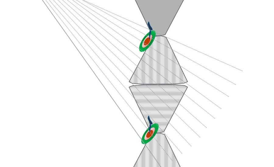
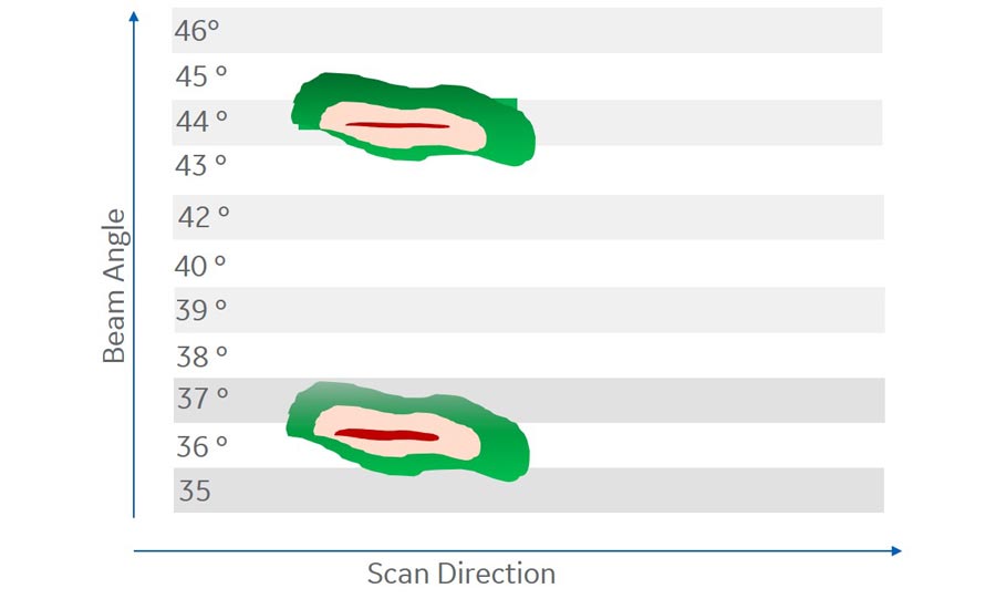
Fig 1 On-Device Angle-Corrected C-Scan
Simplifying Ultrasonic Inspection
Ultrasonic (UT) inspection began as a simple pule-echo technique, where sound waves reflected from a flaw are used to create an image of the location and size of the flaw. With the introduction of Time of Flight Diffraction (TOFD) and phased array, interpretation has become much more accurate and speedier. However, interpretation is often still the domain of UT experts.
Phased array systems rely on the computer-controlled excitation of each element in a multi-element probe in terms of the element’s amplitude and the delay between the energizing of consecutive elements. In this way, the small wavefronts created can be time-delayed and synchronized for phase and amplitude such that a focused, steerable beam is produced. This allows a phased array probe to inspect with variable inspection angles and focusing depths almost simultaneously. As a result, a single phased array probe can perform those inspection tasks normally requiring large numbers of conventional probes or multiple scanning passes. Although TOFD probes can be used in phased array, most systems use conventional pulse-echo, where the dB drop method (3, 6 or 20db drop in amplitude) is used to size and visualise any flaw. However, the problem with this technique is that it provides too much information for the current computing power of a typical UT flaw detector to handle. Consequently, the data projection is simplified for faster up-date so that the on-site inspector cannot visualise the actual location of the defect when using sector or angle linear-based C-scans or B-scans and the raw data is sent remotely to an expert to asses on a remote pc. Typically, inspectors are instructed to select the beam angle at a critical location, such as a weld root, and only that beam can be seen during data acquisition. The inspector can change the beam angle to view other B-scans but data recording must be paused when doing this.
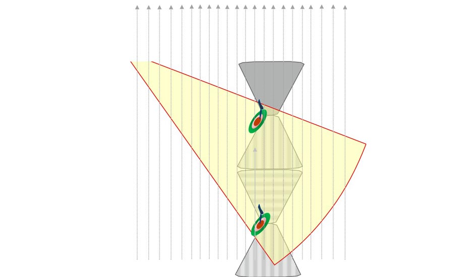
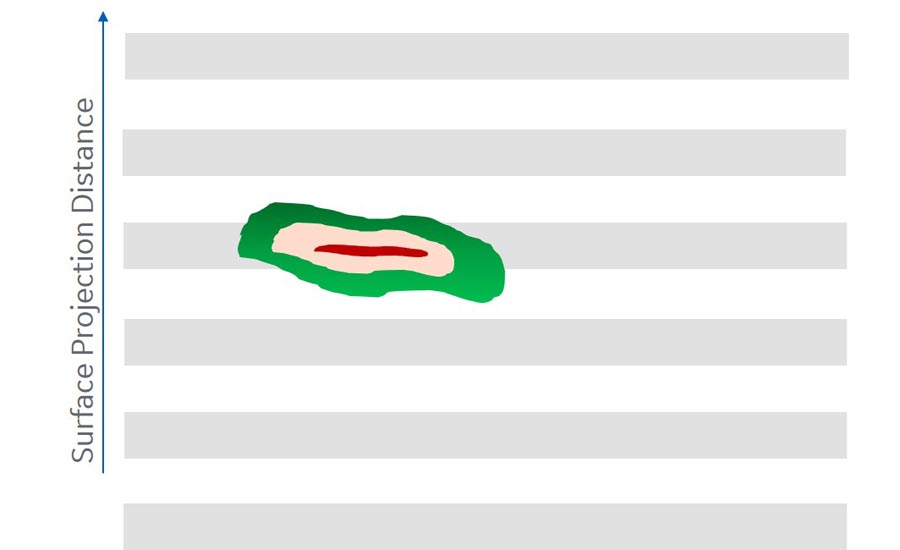
Fig 2. On-Device Volume-Corrected C-Scan
Historically, the remote expert has merged the raw data to create to create a volume-corrected C-scan or B-scan to perform his analysis. Recent developments in ultrasonic systems with faster computing power now allow volume corrected, enhanced images to be created on the inspector’s device. Furthermore, by using volume-based statistics to measure signal amplitudes, defect sizing is made faster and easier
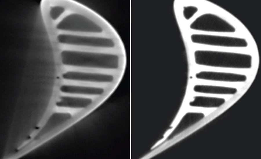
Fig 4. Virtual CT Slices of a Turbine Blade without (left) and with Scatter Correction
Better Remote Visual Inspection
Remote visual inspection is widely used in many engineering sectors. This technique has recently seen the introduction of the first HD 3D measurement-enabled portable video borescope, which can now offer even better HD quality and accuracy in a lightweight but extremely rugged design, which can be used in the harshest of inspection environments.
The basis of the new instrument’s excellent HD quality is its high-intensity light source and superior visual processing to deliver clearer sharper videos and still images directly to the handset. Not requiring the need for multiple tip changes, the quality of these images provides accurate measurement at increased distance, to enlarge the measurement surface area and POD. In addition, the HD-enabled digital zoom allows inspection of very small indications, while on-demand 3D Phase and Stereo Measurement connect with a fully surfaced, point cloud to map, measure and analyze indications and pair with on-device workflows, data management and assisted defect recognition to create access to intelligent data to speed up asset decisions.
Computed Tomography: From the Lab to the Production Line
Computed tomography (CT) has moved on from being purely a laboratory technology to becoming a process control tool, especially in the manufacture of components in aerospace, automotive and the additive manufacturing sectors. A major factor in this has been the introduction of a bundle of CT innovations, bringing down CT inspection times from hours to few minutes at the same result quality level.
The latest developments for increased throughput have been seen e.g. the introduction of scatter radiation artefact corrected efficient cone beam instead of fan beam CT. By a patented combination of hard- and software to automatically remove the majority of unavoidable cone beam scatter artifacts from the CT volume, this provides image quality similar to that achieved with conventional fan beam scanning but at speeds up to 100 times faster.
Another innovation for increased CT throughput is the next generation of high dynamic flat panel X-ray detectors, which combine 100µm pixel size with a unique photodiode design, improving efficiency and sensitivity by up to tenfold compared with conventional, state-of-the art DXR detectors, allowing twice the resolution without impacting on cycle time or doubling the scan throughput.
Last, but not least, throughput optimized high-power CT scans once required larger focal spots to prevent the target material in the X-ray tube of melting. But larger focal spot meant lower image sharpness – and inspection result precision. Innovative high flux targets optimized for thermal conductivity allow doubled power on a smaller spot, hence enabling improved speed or accuracy with doubled CT speed at the same quality or doubled resolution.
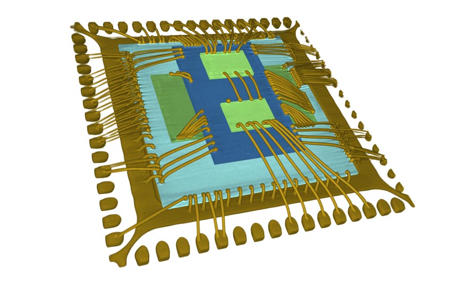
Fig 5. 3D Image of an Electronic Package
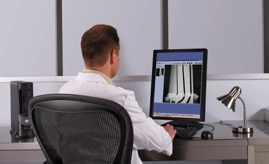
Fig 6. Radiographic imaging.
CT for Nondestructive Coordinate Measurement
CT is also proving invaluable as a dimensional metrology tool. This is especially the case where complex parts like metal or plastic printed components with difficult-to-access, or even inaccessible, internal surfaces, need to be measured. While conventional coordinate measurement methods fail, CT can be used to carry out nominal-actual CAD comparisons, (remaining) wall thickness analysis and dimensional measurements even on internal, hidden surfaces. According to the VDI 2630 standard, reliable metrology results with an accuracy of less than 4 microns can be reached with CT systems equipped with latest metrology techniques such as fully automated calibration workflows and compensation of thermal drift effects.
Industrial Volumetric CT – Seamless Integration with Robotics
Further demonstration of CT’s move to the shop floor is provided by a new fully automated manufacturing line including 100% CT inspection in Asheville, NC, which produces ceramic matrix composite (CMC) components for the aerospace sector. By converting to fully autonomous robotic handling of the parts to be inspected and seamlessly integrating with CT technology, inspection times have been dramatically reduced and the system itself is eminently scalable to meet future anticipated demands.
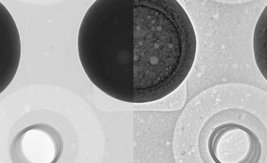
Fig 7. Radiographic Images with and without Flash!
CT in Electronics Manufacture
The traditional industrial sectors for CT have been aerospace and the automotive sector. Now, with increasing product complexity and e-mobility challenges, the electronics manufacturing sector is increasingly switching from 2D automated X-ray inspection (AXI) to high resolution CT NDE. Typical applications include inspection of semi-conductor chips, high-end electronic assemblies, sensors and last, but not least, lithium-ion battery cell and package microfocus CT inspection as well as large component minifocus evaluation of complete battery packs. Such is the emerging importance of this sector that Waygate Technologies has recently opened another dedicated Customer Solutions Center in Seoul / South Korea, covering the full range of advanced CT inspection solutions for the South Korean battery, electronics and automotive industry.
Projecting the Right Image With Digital Field Radiography
Digital field radiography describes radiography used on-site, ranging from film digitization systems to computed radiography and direst digital radiography. Recent developments in software can now maximize the power of portable radiographic imaging systems. New software includes a portfolio of advanced image acquisition and review tools and includes DICOM/DICONDE-compliant data management.
Conclusions
NDE, like all quality control procedures, is often viewed as an irksome add-on cost. However, again like all quality control procedures, it is a necessary cost to ensure the fitness-for-purpose of any item, to ensure customer satisfaction with that item and to ensure the operational safety of the item, whose failure might involve very expensive downtime, litigation or even loss of life. In the manufacturing sector it can also save costs by highlighting flaws in rejects, caused by errors in automated production processes, which can then be rectified. Especially the actual migration of CT from the R&D and quality labs to the production floor as NDE and metrology tool opens great opportunities for 100% control of highly complex or safety relevant components such as additive manufactured parts, batteries or aerospace components while in mass production it allows generation of statistical 3D data to ensure instant process optimization to ensure highest productivity and product quality.
Consequently, it is important that the NDE tools and systems available provide the highest probability of detection and accuracy and can provide understandable data quickly and easily. Recent developments in NDE technology are focused on the never-ending quest to achieve these objectives. NDT
Looking for a reprint of this article?
From high-res PDFs to custom plaques, order your copy today!


