NDT XRD
X-Ray Diffraction
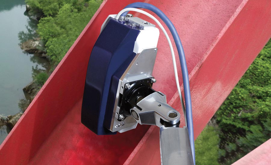
XRD has been applied in industry for many years.

XRD in Use. Courtesy of PulsTec Inc.
X-ray diffraction (XRD) is a nondestructive testing method that has been around for over 100 years. It is used in many industries and it has several specific applications that are very critical. So, what is it and how does it work?
The first thing to understand is that XRD is an actual X-ray based method that is performed only after all the standard X-ray safety precautions and concerns are addressed. But, it is far from conventional X-ray. In conventional X-ray, the X-rays are pointed at an object, they pass through that object with various levels of absorption, and finally they are captured on a film, imaging plate, or digital detector. The result is an image of the object under test. This image is what a doctor or an industrial technician will interpret to determine if everything is acceptable, or if there are any issues.
With XRD, X-rays are pointed at an object at an incident angle, the X-rays then slightly penetrate the material and interact with the atoms. Some portion of the X-rays are absorbed, but others scatter from the material at the same angle at which they were focused. Finally, the diffracted X-rays are captured on a detector of some type (i.e. similar to conventional X-ray). These diffracted X-rays provide a specific pattern of the atoms they interacted with inside the material. This pattern and its intensity are analyzed in software packages to determine atomic and molecular structure of material(s).
For XRD to work, there needs to be an explicit relationship between the angle at which the X-ray's beams interact with the parallel planes of a materials atoms (https://www.merriam-webster.com/dictionary/Braggslaw). The wavelength of the X-rays along with the distance between the crystal planes is key. This relationship allows for a strong diffraction. This is a law of physics called Bragg’s law. Figure 1 shows the relationship of the incident X-rays and the diffracted X-rays.
Now that we know what XRD is, what can actually be done with it? There are several different applications where XRD is very useful and where it has been applied in industry for many years. For this article, we will look at the three main applications: (1) powder analysis; (2) crystallography orientation; and (3) stress measurement.
XRD in Use. Courtesy of PulsTec Inc.
XRD for Powder Analysis
This technique is used across a wide range of industries such as engineering, material science, environmental science, geology, and biology. It requires a fine powder sample of a given material. Because the sample is a powder, there is random orientation of the material sample. To account for this, the sample is irradiated over a given range of angles to ensure that all possible diffraction directions of the atomic lattice can be attained. The diffracted X-rays of all the various angles are collected and they are then processed and analyzed.
The analysis for powder requires a conversion of the diffraction peaks into what are called d-spacings. D-spacings, in brief, are the unique inter atomic fingerprints for all solid crystalline materials. Once you convert the diffraction pattern into d-spacing the data can then be referenced against a master database of standard reference materials for quick identification.
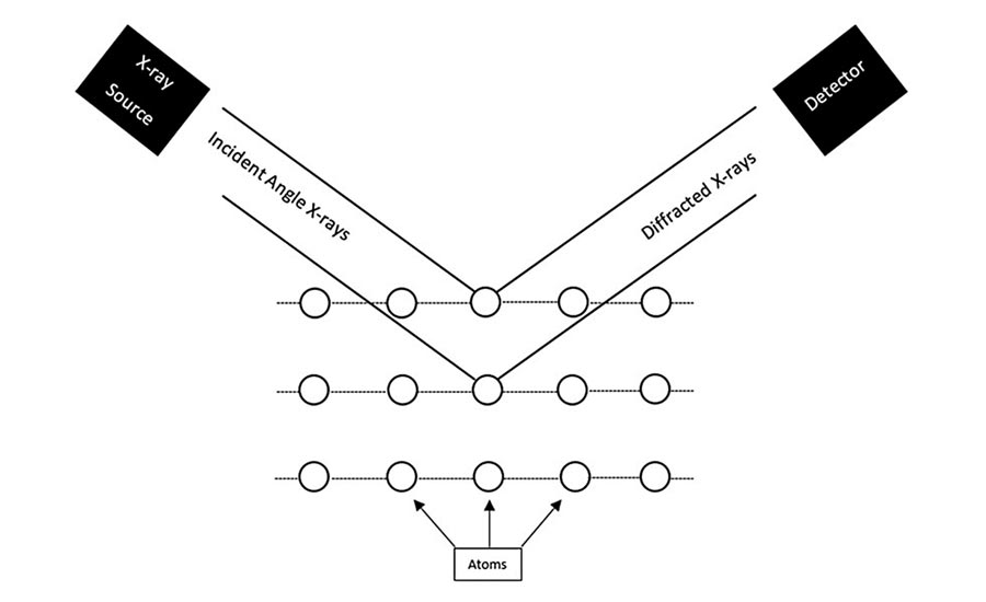
Figure 1. X-ray Diffraction Example
This application is widely used for identifying known crystalline materials. It can also be used for unknown materials as the data will provide key information for properly identifying the unknown material.
As an application example, advanced ceramic manufacturers use this method as both a material determination quality control check and for product consistency validation. Most companies require that each raw material undergo XRD for every material batch manufactured.
Figure 2 provides an identification of the material that is based on the XRD.
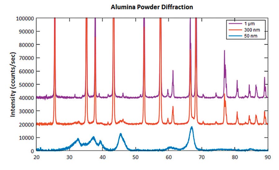
Figure 2. Powder Diffraction D-Spacing Plot. www.ebatco.com/laboratory-services/x-ray-diffraction
XRD for Crystallography Orientation
This is the technique of using diffracted X-rays to determine the atomic and molecular orientation of a crystal. To do this, the X-rays are focused on a single point of a test sample and the diffracted pattern is captured on a variety of different types of either film or detectors. Using only a single diffracted pattern, the data is used to define a sample’s atom plane orientation in correlation to a known reference plane of the single diffraction point. The single point method is the most standard approach. But, this method also allows for samples to be rotated on known reference planes and multiple patterns can be captured to produce a three-dimensional map of the density of electrons within the crystal.

Figure 3: Theta Diffraction Pattern. National Physical Laboratory, Good Practice Guide No. 112 Improving Single-Crystal Orientation Determination for Nickel-Based Alloys.
An application example of XRD using the single point approach is grain orientation measurements of turbine blades. In the aviation industry, single crystal turbine blades have been produced for many decades. These blades are typically operating in the hottest, most stressful, and severe environment inside the engine. Because of this, these blades need to have a specific crystal plane as near to perpendicular to the rotational forces as possible. This plane is what is known as Theta (). This procedure is easily verified by presenting the turbine blade to the X-rays in a fixture that ensures the correct reference direction is irradiated. Once the X-rays are on, the atom lattice is imaged, and the software packages can quickly measure the blade’s Theta plane orientation. In figure 3, the individual atoms and the lattice structures of both the Theta plane and an additional plane, Kappa (), are shown. Notice that the lattices are very structured and that the spacing of the atoms is uniform and easily measurable. The Theta image is showing a nearly perfect angle of zero. If the angle was different from zero, the pattern would be displaced from the center and it could also be rotated. If the Kappa plane was captured instead of Theta, you could easily tell by the images and since the pattern is so different, it would be quite easy to determine.
XRD in Use. Courtesy of PulsTec Inc.
XRD for Stress Measurement
This method is again measuring the crystal lattice, but unlike the orientation measurement, which is focused on lattice position and rotation, this is specifically focused on strain at the atomic level. As a caveat, this is a stress measurement not a strain measurement, but determination of stress requires measurement of some intrinsic property. The XRD stress measurements come directly from strain readings that are calculated and assume a linear elastic distortion of the crystal lattice. In simple terms, this method is measuring the amount of spacing change between the atoms and into the lattice depth.
These measurements are typically performed using advanced software algorithms and have been found to be highly accurate.
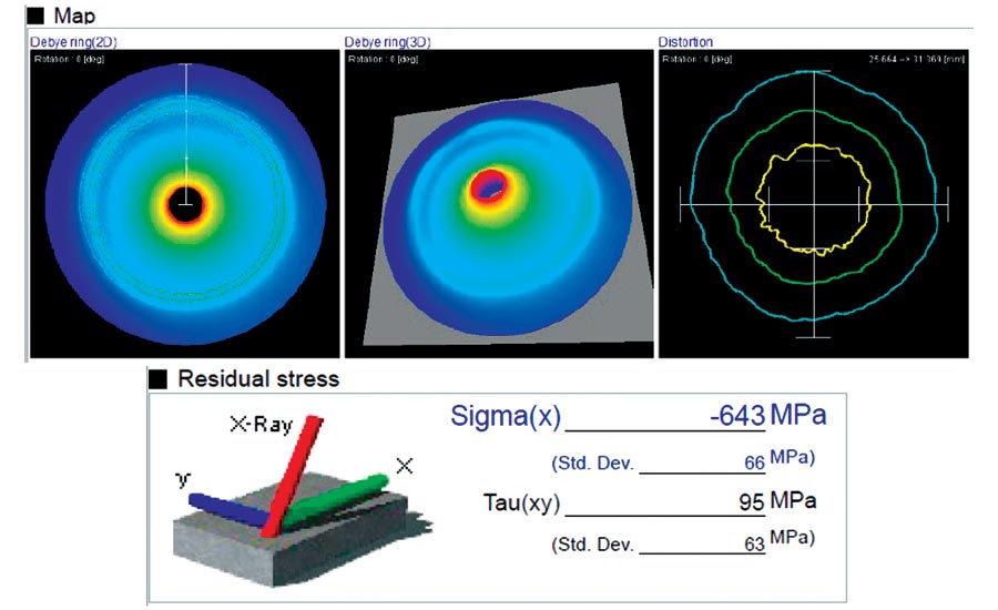
Figure 4: XRD Residual Stress Software Screen. Courtesy of PulsTec Inc.
As an application example, we will look at residual stress. Residual stress from XRD is the arithmetic average stress in a volume of material defined by the irradiated area. This is one of the main uses of XRD in many industries for component manufacturing. Cold working, heat treatment, surface treatment, and any other material altering manufacturing processes are what makes XRD very useful for this application. Any of the mentioned processes will alter the material at the atomic level. Some of these alterations can be critical to a part’s life. There can also be a change of a part’s stress due to fatigue, exposure, and other outside factors, so having an accurate measurement tool is critical.
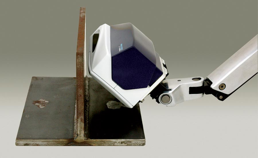
The images throughout this article show a variety of actual XRD applications. As you can see, this method can be used on real world products and, in some cases, has been brought out of the lab and into the field with portable XRD options.
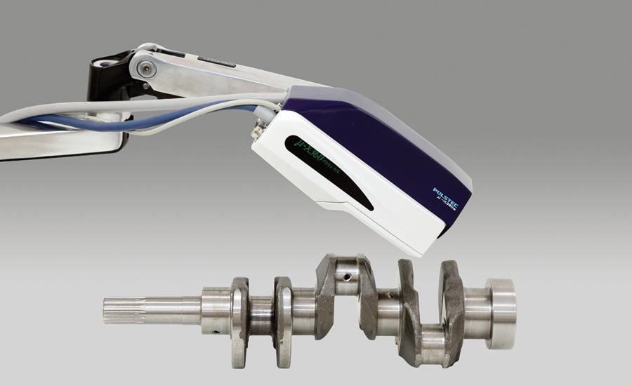
Figure 5: XRD in Use. Courtesy of PulsTec Inc.
In summary, X-ray diffraction is an NDT method that has been around for over 100 years. It is used in many industries and it has several specific applications that are very critical. It is very different from conventional X-ray. But, it is an X-ray-based method that needs to be performed only after all the typical X-ray safety precautions and concerns are addressed. The method has varied uses and plays a significant role in research, manufacturing, and quality inspection. As innovative technologies arise, new applications for XRD will continue to present themselves. As is the case with the emergence of the new age of additive manufacturing (AM). In this fast-growing, ever-expanding industry, XRD could soon find itself crucial as a primary target for understanding the material state of AM parts. NDT
Looking for a reprint of this article?
From high-res PDFs to custom plaques, order your copy today!


