The Veteran of Noncontact Metrology
Is air gaging still relevant in the 21st century?
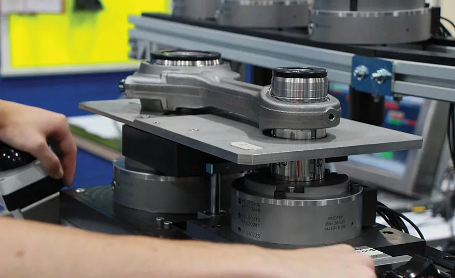
Connecting rods
Pneumatic metrology can provide solutions that give over 20 measurements per part in under two seconds. That is a speed that eclipses what can be accomplished on a CMM, given ten times the measurement time.
It seems that everyone is interested in noncontact gaging these days. Laser scanners, structured light, confocal chromatic sensors, and CCD cameras have all made significant advances in the last decade, leaving us to wonder if this century old technology is still useful today. In the case of air gaging, the long-time staple of noncontact metrology, the answer is a resounding YES!
Nearly 100 Years of Development
Once called pneumatic gages, a term that is less frequently used today, air gaging dates back to the early 20th century where it was used to validate carburetor jets in France. The idea of using an air restriction to provide back pressure led to advancements that gave us the air gaging solutions we use today.
Air gages provide a reliable and highly accurate production measurement system when optical and tactile gaging are impractical, due to heat, coolant, swarf, and other byproducts of the manufacturing process.
Air gages are:
- Fast
- Accurate
- Repeatable
- Resistant to part contamination
- Reliable, with very little required maintenance
Design
All air gaging uses a combination of air flow and pressure through a tooling orifice, or “nozzle,” fed to a transducer. Typically, a computer monitor (or HMI) is incorporated to allow the operator to view the results. Mechanical dial and column gages are less common than they once were, but are still in use for bench gaging. Today, they are likely to use LED displays in place of dials and float columns.
Types of Air Gages
There are three types of air gages you are likely to encounter today:
1. The Air Flow Gage
Using a high rate of air flow, this type of gage is best suited for applications where long air hoses are needed, such as an axle tube. In this gage, a float moves vertically within a flow meter tube, providing an easy to read display. Two masters are used for calibration of the system.
Disadvantages of the air flow gage include the added complexity of changing flow tubes and scales for different applications, higher air flow requirements, and a larger orifice/nozzle. Larger nozzles mean that the air flow orifice must be kept closer to the part.
Flow gages can also be used where the flowmeter must be located some distance from the workstation.
2. The Back Pressure/Bleed Gage
In this gage system, an air pressure regulator keeps the pressure to the system constant, ensuring that the gage gives linear accuracy throughout the measurement range. The inlet air line for this system must have enough flow for the pressure regulator to operate properly. The regulator allows the pressure to be changed for different tooling, making this a very versatile gage system. As the goal is a very linear gage, min/max calibration masters are used. These masters reflect the range of expected measurements and correct for tooling wear (within limits).
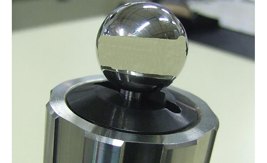
3. The Differential Air Gage
For this gage, air flow is split into two paths. The first path leads to the tooling orifice. The second path goes to a balance or “zero” valve which in turn sets the pressure balance to the tooling orifice. A comparison between the zero path and the tooling orifice provides the results, hence the “differential” name. A differential pressure transducer is used to compare the pressure from the two air paths.
The differential air gage provides very accurate results if the tooling is kept in good repair. However, it is more sensitive to wear or restriction around the measurement orifice. This is due in part to the use of only one calibration master being used for setting the zero point. The farther the part size varies from this master, the less consistent the results.
FUEL INJECTORS
With tolerances in some cases of less than a micron, air gaging is the only technology that can meet the task. Since the primary function of the injector is to provide flow an air gage solution is ideal. As we ask more and more out of the internal combustion engine (ICE), perfect injector flow is a must.
The Gage That Cleans
Today, air gage system pressures can be as high as 42psi. Using pressurized air circuits means that parts can be introduced in a non-clean state while still allowing accurate repeatable measurement results. This is possible because as the part is being introduced into the air tooling, air bleeding from the measurement jets “blows” the contaminants away from the measurement surface (within limits). If the part is exceptionally dirty, complementary “cleaning” jets can be manufactured into the air tooling for additional pre-measurement blow-off.
Part Characteristics
Some of the characteristics that can be measured with a properly designed air gage system include:
- Diameters
- Taper
- Barrel
- Hourglass
- Lengths/Widths
- Dimensional Clearances and Interferences
- Perpendicularity
- Parallelism
- Concentricity
- Coaxiality
- Ovality
- Conicity
- Hook/Bell Mouth
- Sub-Micron Size Classification for Part Matching
Max/min form measurements can be performed with some limitations. Results will depend on consistency of positioning as well as the natural filtering that occurs due to the size of the tooling orifice. If your application requires roundness and/or cylindricity, other technologies may be better-suited.
Air gages are often the right choice when tolerances are between 1 and 100 microns. They are suitable for IT2 and even IT1 tolerance grades if roughness is controlled (.8 µm Ra typ.).
Air gaging can achieve accuracies to 0.1 µm, repeatability up to 0.2 µm, for tight tolerances under 2 µm, in a production environment!
MEDICAL
Without moving parts, air gages are well-suited to clean room environments. Because the measurement orifice does not touch the part, the witness marks sometimes present with tactile gages, are not a factor.
Applications
Air gaging is typically more application-specific than general-purpose solutions like a CMM. However, one of its core strengths is the interchangeability, or adjustability, of different components, allowing a much greater range of flexibility than it would otherwise be capable of achieving. A good example of this would be a system designed to measure connecting rods. Using a simple length adjustment block, the center-to-center distance between the pin and crank diameters can be modified, allowing a much greater range of sizes to be measured. Combine this with interchangeable air tooling and you get a highly flexible machine capable of measuring a much greater range of part sizes.
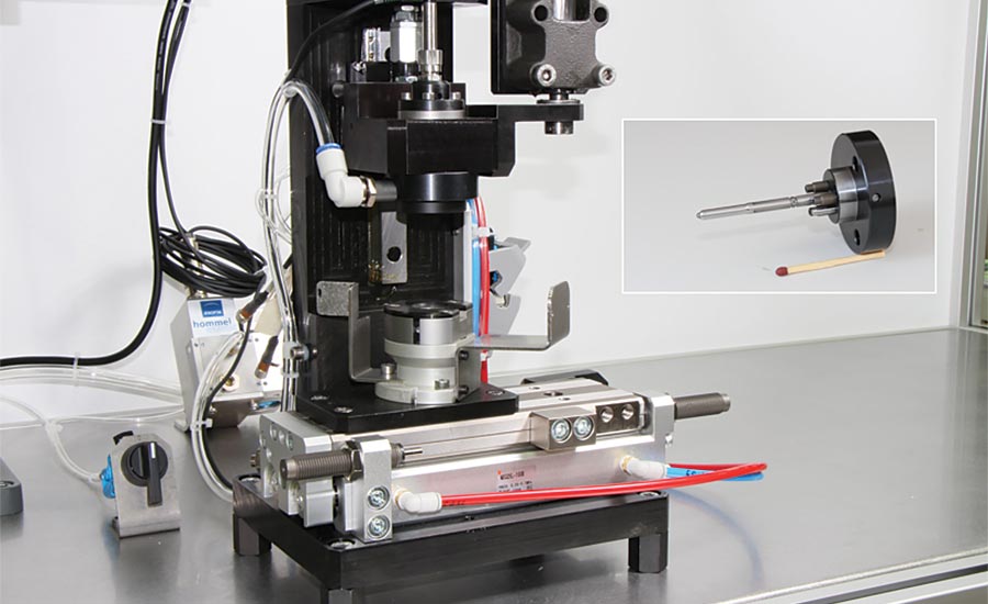
Capable of measuring inner diameters as small as 0.8mm (difficult using any other technique), air gage tooling can be custom-manufactured using single, multiple, or annular air jets to cover the full range of dimensional and geometric measurement characteristics. Unlike contact gaging which requires fragile “flex fingers” to measure small-bore diameters, air tooling has no moving parts, improving overall reliability. The lack of moving parts along with simplified designs using wear resistant materials (carbide, TCIN coating, etc) for tooling, significantly reduces maintenance costs and improves reliability of the system.
Resolution and repeatability depend on the style and quality of the manufactured tooling, the type of air jets (round or rectangular), the style and quality of the air-to-electronic converters, as-well-as the measured value. Resolutions of 0.01µm are achievable using basic off the shelf equipment. Capable of repeatability ≤0.1µm (very difficult to achieve through contact style gaging), air gaging consistently provides an accurate and robust form of metrology.
Sourcing Your Gaging Solution
Components to build your own air gage system, as well as complete metrology solutions, are available from a variety of sources. Unless you are a skilled gage builder, the author recommends you go with a recognized air gage supplier for your first system. A properly designed gage will save you many headaches when it comes time to perform the GR&R with your customers, and will provide additional benefits, including:
- Software for Statistical Process Control (SPC)
- Integration with Industrial Controls
- Field Service and Software Support
- Upgrades and Replacement Tooling
For complex parts needing a variety of quality checks, custom solutions incorporating multiple noncontact sensors are also an option.
Conclusion
Significant advancements have been made in noncontact pneumatic metrology since its infancy in pre-World War II France. The advancement of electronic transducers and display technology, as well as the incorporation of industrial controls and software, have allowed the humble air gage to keep pace with modern manufacturing requirements. Air gages will remain a viable technology into the coming decades and possibly, the NEXT century. Q
Looking for a reprint of this article?
From high-res PDFs to custom plaques, order your copy today!


