Exploring the benefits of noncontact thickness metrology
Noncontact thickness metrology solutions have become a necessity for the manufacturing sector.
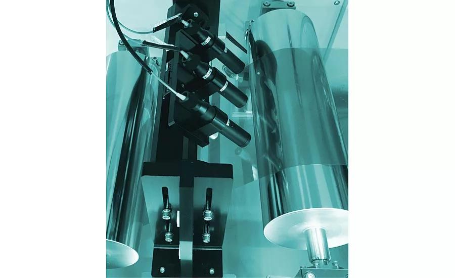
Inline image for single sided web thickness inspection
If you were to ask an assembler at a Tesla factory how they measure the diameter of a piston, the response could very well be “what’s a piston?” If the same question were asked, a traditional combustion engine assembler would likely exclaim “with calipers, of course!” If we are to probe and delve into the quality control limitations associated with contact thickness measurements, we are likely to witness that the use of such instruments results in operator-based measurement variability, limited sampling of the part being manufactured, and potential damage to the part. It is largely for these reasons that noncontact thickness metrology solutions have become a necessity for the manufacturing sector. In this article, we will demonstrate two distinct methods that effectively measure part thickness without making any contact. We will first describe the benefits of using chromatic confocal technology for one-sided measurements, then the benefits of using triangulation sensor technology for dual-sided profiles.
Chromatic confocal point sensors are widely used as direct imaging profilometers for surface texture analysis, dimensioning and tolerancing, and height measurement. These sensors are made up of a polychromatic source, optics that disperse this white light, and a confocal arrangement. When the dispersed wavelengths are projected and subsequently reflected from a measurement work piece, a single in focus wavelength returns to be decoded for distance via its confocal arrangement. If visibly transparent materials are being inspected, however, two confocal peaks are returned. The separation of these peaks corresponds to the optical thickness of the sample, which can be used in conjunction with knowledge of the material’s optical properties to determine a physical thickness. This one-sided noncontact thickness measurement technology is a key advantage for in-line thickness control of roll to roll processes.
In a roll to roll process, material undergoes a series of steps for the creation of electronic devices on flexible plastic substrate. One of these substrates is a transparent PET composite. Since the substrate is part of the electrical device, its thickness must be well controlled. By measuring the substrate thickness as it’s being manufactured, costly value-added processes on defective material can be avoided. A one-sided thickness measurement solution has many advantages for such an application. Some of these advantages are:
- Reduced complexity of sensor placement – probes can be positioned at their working distance above the web without the mounting concerns associated with a paired probe.
- Ability to log data automatically allowing for real-time statistical process control.
- Absence of individual sensor drift (present in dual sensor arrangements).
- Sensor spot alignment not required. In order to accurately report substrate thickness with a paired arrangement, both sensors would need to be aligned both horizontally and orthogonally. One-side approaches eliminate the need for this.
- Absence of paired sensor acquisition synchronization. In order to accurately report substrate thickness with a paired arrangement both sensors would necessarily have to be measuring at the same location at the same time.
When opaque media must be measured, laser-based triangulation line sensors are a quick yet accurate option. These sensors use a mono-chromatic source to project light through a series of optical elements and onto a workpiece. Diffuse reflection at a pre-defined angle is then focused onto a CMOS detector for decoding distance. Since the principle relies on the capture of diffuse reflected light over a narrow angular band, this technology is best suited for measuring flat workpieces.
Several quality assurance applications have benefited from dual-sensor thickness metrology. One such application is the measurement of metal or graphite fuel cell plate parallelism. Fuel cells are typically stacked together to form a larger power fuel cell stack. Capturing the parallelism of each cell plate allows for controlling the total parallelism of the eventual stack. It then also allows for larger plate parallelism by selecting those cells that together minimize total stack parallelism.
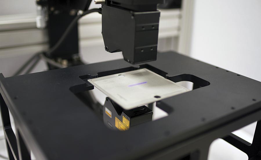
Opaque media thickness inspection
The configuration for such a metrology system would be composed of XY translation stages for either sample or sensor movement, and two opposing vertically mounted triangulation sensors that are aligned both horizontally and orthogonally. The measurement workpiece is placed in between the two sensors at a length of the sensor working distance from each sensor. Stage encoder feedback is synchronized with data acquisition thereby allowing for calculation of thickness at each scanned location of the sample. Sample thickness at each location is determined by subtracting the distances from the sample to each sensor from the total distance between the two sensors. The distances from sample to sensor are typically acquired at kHz rates, and the total distance between the sensors is defined as part of the system configuration.
In conclusion, noncontact thickness metrology methods are quickly replacing contact-based thickness solutions. Enhanced process control with automated data collection, fast time to results, and sample integrity are just a few of the factors driving this change. Visibly transparent media are well suited for single sided thickness measurements, whereas opaque media thickness measurements are most efficiently performed using line triangulation sensors. As consumer demand around the world increases, manufacturers are constantly searching for ways to raise the bar in terms of efficiency and quality control. As developments are being made daily, noncontact thickness measuring is quickly becoming more sophisticated, less expensive, and more accessible. By subscribing to noncontact thickness measuring technology, we will see even more advancements in the manufacturing sector, and thus be more prepared to meet the various needs of our rapidly changing world.
Looking for a reprint of this article?
From high-res PDFs to custom plaques, order your copy today!


