Developments in Machine Vision Camera Interfaces
A number of data transfer hardware interfaces have been developed specifically for the machine vision sector over the years, including cameralink, GigE vision, USB3 vision, CoaXpress and Cameralink HS.

Figure 1. Multizone inspection controlled via a single workstation (GigE Vision)
The choice of camera data interface is a vital consideration both in traditional PC-based machine vision systems and in the increasingly important area of embedded vision. Higher and higher resolution CMOS image sensors and increasing inspection speeds require large amounts of data to be transferred between the camera and processor. The bandwidth needed for the application and the image data transmission distance are critical requirements, although other factors such as triggering accuracy and latency in the system are also important. A number of data transfer hardware interfaces have been developed specifically for the machine vision sector over a number of years, including CameraLink, GigE Vision, USB3 Vision, CoaXPress and CameraLink HS (Table 1).
| Interface | Image Data Throughput | Cable length (copper) | Frame Grabber |
| GigE Vision | 115 MB/s | 100 m | No |
| CameraLink | Up to 850 MB/s | 4m-10m* | Yes |
| USB3Vision | 3-400 MB/s | 3-5 m | No |
| CameraLinkHS | 2100/3300 MB/s | 15 m | Yes |
| CXP-6 | 625 MB/s | 40 m | Yes |
| CXP-6 x4 | 2500 MB/s | 40 m | Yes |
Table 1. Camera interface performance parameters
* Dependent on configuration and clock speed
These all rely on the GenICam standard to provide generic software interfaces to ensure complete plug & play functionality for imaging applications. Each standard will require the use of particular cable types, connectors and other components, which form an integral part of the vision system structure. Since vision system builders will often only revisit a design around once every five years, changing the infrastructure once a particular interface has been implemented can be difficult and costly. Thus recent developments utilizing the GigE Vision platform (2.5GigE, 5GigE and 10GigE) and the CoaXPress platform (CXP 2.0) enable performance enhancements to be implemented without major changes to the system. For embedded vision applications, USB3 has been the most commonly used with the commercial MIPI CSI-2 interfaces growing in adoption.
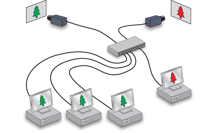
Figure 2. Remote data transmission to multiple workstations using existing network (GigE Vision)
Building on GigE Vision
The GigE Vision standard is managed by the AIA trade association (www.visiononline.org). It allows the use of existing low cost Ethernet cables, connectors, switches and other components for transmitting image data over distances up to 100 meters using copper cable and more with switches and fiber adapters. Gigabit Ethernet also offers the potential for creating different implementation models and complex networking topologies. These include inspection ‘networks’ split up into different functional zones, but all controlled by a single workstation (Figure 1). Another option is to use existing network structures to transmit data from remote locations to any number of different workstations. As each camera is independently locatable on a network via its IP address, it can be viewed, controlled and monitored from any PC on the network (Figure 2). Multicast connectivity opens up scalable solutions with image data simultaneously transmitted to multiple processing PCs. GigE Vision 2.1 also includes improved real-time synchronization of multi-camera systems utilizing the IEEE 1588 Precision Time Protocol and features multi-part transmission which enables the transmission of more complex data structures used in 3D imaging or any application which would benefit from a three coordinate data structure. While GigE Vision offers undoubted flexibility, the maximum bandwidth of 115 MB/s has been a limiting factor for some applications. Individual camera manufacturers have offered increased bandwidth based on parallel cabling configurations (LAG) or proprietary software approaches, however the introduction of NBASE-T technology has significantly enhanced the bandwidth within the GigE Vision framework. NBASE-T technology from the NBASE-T Alliance, is an extension to the IEEE 802.3 Ethernet standard and increases data transmission up to speeds of 2.5, 5 and 10 Gb/s for 2.5BASE-T (2.5 GigE), 5BASE-T (5 GigE) and 10BASE-T (10 GigE) respectively (Table 2).
| Interface | Image Data Throughput | Cable length (Cat5e) | Cable length (Cat6a/Cat 7) |
| GigE Vision | 115 MB/s | 100 m | 100 m |
| 205 GigE | 280 MB/s | 100 m | 100 m |
| 5 GigE | 570 MB/s | 100 m | 100 m |
| 10 GigE | 1100 MB/s | 55 m | 100 m |
Table 2. NBASE-T interface performance
Since the Ethernet networking stack is divided into a number of different layers which are isolated from each other, camera manufacturers have been able to create 2.5 GigE, 5 GigE and 10 GigE interface solutions that communicate using the GigE Vision standard, meaning that the technology is future proofed. Virtually any modern PC can be upgraded for these standards using a relatively inexpensive Network Interface Card (and driver) with GigE Vision-compliant software also being compatible with NBASE-T. Data transmission distances of 100 m are possible for 2.5 GigE and 5 GigE and 55 m for 10 GigE using Cat 5e cable. Cat 6a and Cat 7 cable enable 100 m transmission for all three platforms or significantly more when using fiber adaptors and configurations. Since using 10 GigE at full speed on copper cable can generate a lot of heat as 10 GigE chipsets have a high power consumption, other system level challenges need to be considered if the full speed of the interface is required.
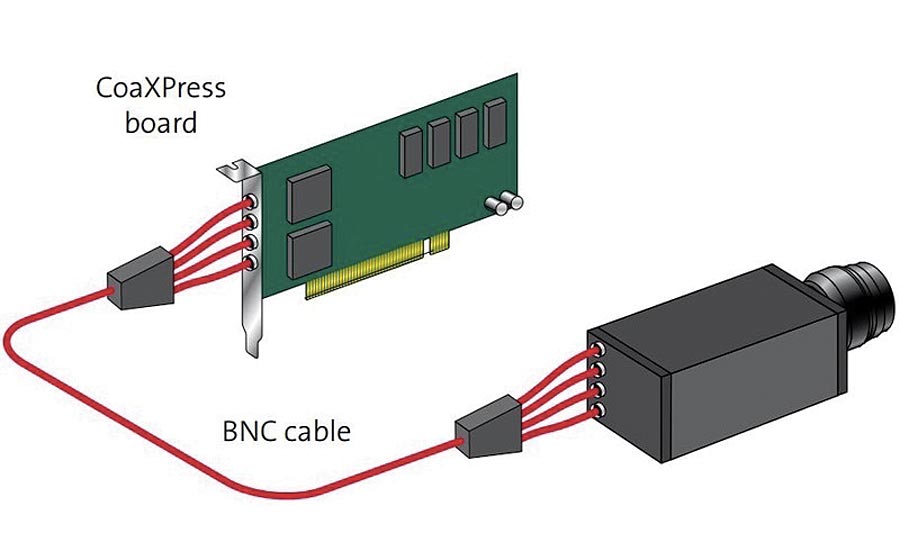
Figure 3. CoaXPress 4 lane configuration
Going for speed
While the introduction of NBASE-T technology has significantly increased the bandwidth for GigE Vision systems, many applications require even more. For those that also need long data transmission distances, the CoaXPress standard, administered by the Japan Industrial Imaging Association (http://jiia.org/en/), offers considerably greater bandwidth, while utilizing coaxial cable which is used extensively in industrial, medical and defense applications. CoaXPress is an asymmetric high speed point to point serial communication standard which requires a frame grabber and is scalable over single or multiple coaxial cables. A single cable can transmit up to 6.25 Gb/s from the camera to the frame grabber over distances up to 40 m which is equivalent to approximately 5 or 6 times the standard GigE bandwidth and exceeds even 5GigE. This can be further increased to 25 Gb/s using four parallel cables, or lanes (Figure 3). However in 2019, CXP 2.0 was released, which effectively doubles the lane performance compared to CXP 1.1, giving up to 12 Gbits/s using a single lane (CXP-12) and 50 Gbits/s for a four lane system (Table 3).
| Interface | Image Data Throughput | Cable length (copper) | frame grabber |
| CXP-12 | 1250 MB/s | 30 m | Yes |
| CXP-6 | 625 MB/s | 60 m | Yes |
| CXP-12 x 4 | 5000 MB/s | 30 m | Yes |
| CXP 6 x 4 | 2500 MB/s | 60 m | Yes |
Table 3. CXP 2.0 transmission distance examples
With one lane of CXP 2.0 providing 12 GBits/sec and 10 GigE operating up to 10 GBits/sec, CXP 2.0 starts where 10 GigE finishes. CXP 2.0 also brings higher trigger rates and improvements in cable length and data sharing as well as an increase in reliability and reporting. Coaxial cables were commonly used in analogue camera imaging applications, providing a cost-efficient and robust solution with marginal signal loss over long cable lengths and are also used in the HD-SDI broadcast standard. Thus some (though not all) legacy analogue systems with coaxial cable can be upgraded to CXP relatively straightforwardly. CXP 1.1 uses BNC or DIN 1.0/2.3 connectors, while CXP 2.0 requires micro BNC connectors. Both CXP 1.1 and CXP 2.0 cameras are compatible with CXP 1.1 and CXP 2.0 frame grabbers, but CXP 2.0 performance is only achievable when both the frame grabber and the camera support the standard. Data, control, real-time trigger and power are all provided over the same cable. CXP 2.0 also introduces a variety of operational technologies including data that can be simultaneously streamed to more than one host and up to four cameras can be connected to a single frame grabber. The 40m transmission distance is extended to 60m for CXP 2.0 operating at the 6.25 Gb/s bandwidth normally associated with CXP 1.1 while double speed can be achieved at 30m. CXP 2.0 cameras are approximately the same price as CXP 1.1 cameras, while a four lane CXP 2.0 frame grabber is around 20% more expensive than a CXP 1.1 version. However, since only half the lanes are needed in CXP 2.0 for the data rate, a two lane frame grabber will be sufficient and these are approximately 30% cheaper that the four lane versions. So for like for like performance CXP 2.0 will be cheaper than CXP 1.1. At present limited cameras are available at the top end of CXP 2.0 and the price will be driven by the sensor cost.
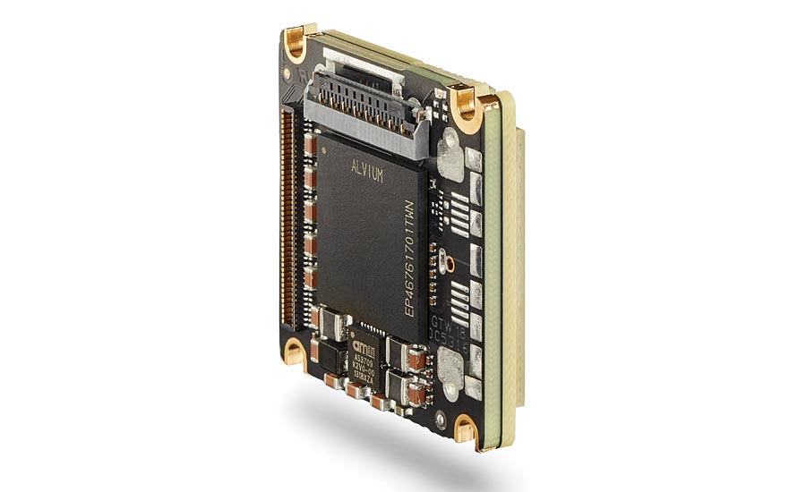
Figure 4. Board level camera with MIPI-CSI2 interface. Courtesy of Allied Vision
Embedded systems
For embedded vision systems bandwidth is just as important as for PC systems but transmission distances are generally much less of an issue as the sensor and processor tend to be closely coupled. Since embedded vision solutions generally incur high development costs, they are best suited for high volume applications where component costs can be kept low and the development costs spread over many units. The two camera data transmission interfaces most widely used in embedded systems are MIPI CSI-2 and USB3.1. MIPI CSI-2 is a specification of the Mobile Industry Processor Interface (MIPI) alliance (a global organization serving industries that develop mobile and mobile influenced devices) and is used extensively in mobile devices such as smart phones and tablets to connect the sensor to the processor but is not part of a machine vision standard interface. Many embedded processors include a direct physical MIPI camera interface. The CSI-2 protocol contains transport and application layers and natively supports D-PHY and C-PHY. CSI-2 D-PHY offers up to 2.5 Gb/s per lane with four lanes up to 10 Gb/s compared to 5 Gb/s for USB3.0/3.1 (https://www.mipi.org/specifications/csi-2). Other factors such as the integration effort required and the load on the host (Table 4) are also important considerations for embedded applications.
There is an increasing availability of the MIPI CSI-2 interface on embedded processor boards and both board-level and housed cameras featuring MIPI CSI-2 are available.
| CSI-2 D-PHY | USB Vision | GigE Vision | |
| Bandwidth | Highest | High | Medium |
| Cable Length | Up to 0.6 m | Up to 0.8 m | Up to 100 m |
| Control | Difficult | Easy | Easy |
| CPU load on host | Low | Medium | High |
| Available on embedded processor boards | High | Medium | Medium |
| Software | Complex* | Easy | Easy |
| Cost | Low | Medium | Medium |
| Size | Very Small | Small | Medium |
Table 4. Interfaces for embedded vision
* lack of driver software prevents easy integration. Future Genicam support will simplify this.
Continuing development
As countries begin to emerge from post-pandemic recessions, the ability to improve vision systems based on existing infrastructure is key in keeping costs down so the availability of NBASE-T and CXP 2.0 interfaces take on even greater importance. The Ethernet Technology Consortium (https://ethernettechnologyconsortium.org/), established to develop 25 Gbps and faster Ethernet specifications, have developed a low-latency forward error correction (FEC) specification for 50 Gbps, 100 Gbps and 200 Gbps Ethernet networks which could eventually pave the way for higher bandwidth GigE Vision systems. For embedded systems Genicam transport layer support for MIPI CSI-2 is getting close to availability, making integration of these lowest cost processor–camera modules easier to develop and will have a positive effect on the time to market for embedded vision applications. In addition, the USB 4 specification was published in late 2019 but will probably not appear in devices until late 2020 or early 2021 so neither interfaces nor cameras are yet available. V&S
Looking for a reprint of this article?
From high-res PDFs to custom plaques, order your copy today!


")
