Keeping Up Standards in Machine Vision
The use of industrial vision as part of Industry 4.0 and smart factories has been discussed extensively in recent years, but requires machines to speak the same language.
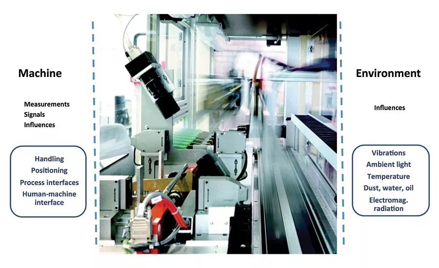
Figure 1. Machine vision system selection influences (1)
Machine vision systems consist of several component parts, including illumination, lenses, camera, image acquisition and data transfer, and image processing and measurement software. There are a number of machine vision standards in use which provide commonality for certain parts of the system, but it is also important to consider the system as a whole, including external machine and environmental influences and conditions. Standards are developed by experts of the machine vision industry to ensure high quality and relevance to the sector. However they take time to be developed and ratified for use, and then in turn it can takes time for industry to adopt a new standard. For example, OEM system builders only revisit a design maybe once every five years, so if the standard in use is working appropriately, the design is unlikely to change unless there is a significant performance or price advantage by changing to a new standard. This article will review the adoption of some of the newer standards to emerge and look at some that are in the pipeline as well as an overall system standard.
EMVA1288 sensor and camera standard
EMVA1288 is administered by the European Machine Vision Association (EMVA) and is useful for both manufacturers and users of sensors and cameras. It creates transparency by defining reliable and exact measurement procedures as well as data presentation guidelines that makes the comparison of cameras and image sensors much easier. It can be applied to all machine vision cameras. The standard data format features a photon transfer curve, a signal-to-noise ratio curve and a list of measured parameters together with a number of calculated parameters. Users can therefore compare cameras according to the parameters that are most important to their particular application.
Camera Interface standards
Hardware data transfer capabilities are particularly important in applications where image data are being transferred back to a host computer for processing and measurement. Two key parameters are bandwidth and the distance over which image data can be transmitted, as well as costs, of course. There are three basic connection types, which have different standards. These are network (GigE Vision), frame grabber (Camera Link, Camera Link HS and CoaXPress) and plug and play (USB3 Vision). Launched in 2006, GigE Vision became very popular, particularly in factory installations, where the use of Ethernet cabling and components is common practice, and because images could be transmitted over distances up to 100 meters without repeaters. However with the availability of higher and higher resolution CMOS image sensors and increasing inspection speeds, the amount of data needing to be transferred has increased significantly. The GigE Vision data rate of <110 MB/s became a limiting factor in some applications. The use of systems requiring frame grabbers such as Camera Link, Camera Link HS and CoaXPress, offers significantly higher bandwidth, but generally shorter basic transfer distances and higher cost. With a data rate >2400 MB/s CoaXPress is comfortably the fastest and makes use of simple Coax cable but transfer distances are less than 100 meters.
The arrival of USB3 Vision in 2013 offered improved bandwidths compared to GigE Vision and low costs, but transfer distances are less than five meters without repeaters. Nevertheless USB3 Vision meets the vision industry’s GenICam standard and has been adopted in many faster applications that only need shorter cable lengths. The attraction of the Ethernet connectivity however has led to a number of developments. Different manufacturers have looked at ways of boosting standard GigE Vision capabilities, ranging from link aggregation to proprietary software approaches. A link aggregation camera uses two cables to connect to the host computer and this is seen as one connection at twice the normal speed. A proprietary software approach uses sophisticated pixel analysis and processing so that each pixel is comprised of fewer bits for encoding, bringing faster data transmission. The improvement in data transfer rate can be 1.5x the standard throughput.
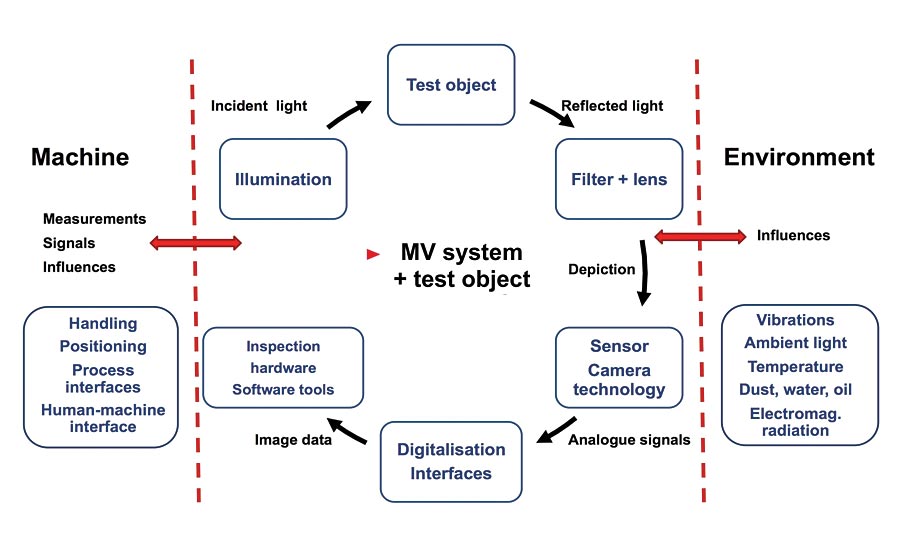
Figure 2. Machine vision system selection influences (2)
The latest development, however, is the use of 2.5, 5 and 10 GigE Ethernet which allow users to get the benefit of significantly increased data throughput without the expense and difficulty of replacing existing Ethernet cabling. These are extensions to the IEEE 802.3 Ethernet standard and increase data transmission using industry standard CAT 5e cable to speeds of 2.5 and 5 Gbp/s and to 10 Gb/s using CAT 6A cable respectively whilst maintaining data transmission distances up to 100 meters. While 10 GigE would appear to be the most attractive having the highest data transmission of the three, the high power consumption of 10GigE chipsets has meant that 10GigE Vision cameras require significant heat sinking, making them larger and heavier than others. 5GigE Vision cameras are now commercially available and some provide even faster data transfer than 5 Gb/s by using the proprietary pixel encoding process, which means that they can offer data rates approaching 10GigE Vision levels, without the heat dissipation issues.
Upcoming standards
The use of industrial vision as part of Industry 4.0 and smart factories has been discussed extensively in recent years, but requires machines to speak the same language. To this end, the VDMA (the Mechanical Engineering Industry Association in Germany) has just released the OPC UA Companion Specifications for Robotics and Machine Vision. OPC UA is a platform-independent, open standard for machine-to-machine communications. The Companion Specification for Machine Vision provides a generic model for all machine vision systems, from simple vision sensors to complex inspection systems. It allows the control of a machine vision system in a generalized way, abstracting the necessary behavior via a state machine concept. It handles the management of recipes, configurations and results in a standardized way, whereas the contents stay vendor-specific and are treated as black boxes.
The EMVA has recently also announced the planning of two new standards. The first is an Open Lens Communication Standard that aims to create a standard electrical connection between the camera and the lens providing a standard connector, standard voltage, standard communication protocol and standard naming of the parameters; as well as providing feedback from the lens to the camera. The second standard is an Embedded Vision Interface Standard. This aims to build on and coordinate between the already existing standards SLVS EC which is hosted by the Japan Industrial Imaging Association (JIIA), and the standard MIPI CSI-2 for mobile devices. The new Embedded Vision Interface Standard will add so far missing functions in these standards, e.g. define a high-level protocol, drivers and standard connectors to plug a sensor module onto a processor module.
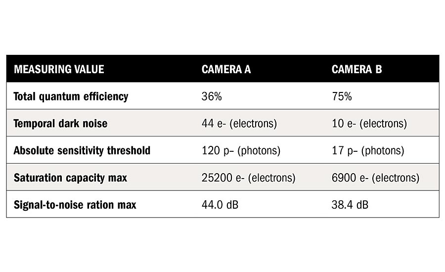
Figure 3. EMVA 1288 comparison of two cameras. In poor lighting conditions, for example, camera B performs better because of the low noise level and good quantum efficiency
Planning and specifying a complete machine vision system
The capabilities offered by machine vision have grown exponentially as technology continues to deliver improved performance in all areas. The overall complexity of the system is determined by the specific application requirements and specific environmental conditions. Planning, specifying and implementing a machine vision system that is fit for purpose should involve more than simply choosing the most robust machine vision components. One way is to make use of the VDI/VDE/VDMA 2632 series of standards for machine vision, published by the VDI/VDE Society Measurement and Automatic Control, developed in conjunction with VDMA Machine Vision in Germany. Part 1 covers basics, terms, and definitions, describing the principles and defining the terms necessary for the use of image processing systems. It defines a consistent terminology for all cooperation partners. Part 2, however, is the ‘Guideline for the preparation of a requirement specification and a system specification’ which places particular emphasis on the representation and description of influencing factors as well as on their effects. This framework begins the specification process by evaluating the application in detail. This will include:
- Identifying the exact measurement task to be undertaken
- Identifying the exact objective of the testing, characteristics to be validated, specimen parts to validate, special requirements
- Identifying all the details about the test object such as range of types, preliminary processes, object contamination, thermal/ mechanical object stability
- Accurately describing the scene in terms of positioning, machinery situation, any disturbing environmental influences
- Accurately describing the process including process integration, interfaces, spatial constraints, operating modes
- Determining any additional information, such as the human-machine interface, operating concept, visualization
Following the VDI/VDE/VDMA 2632 process not only allows the determination of an optimized solution but ensures that if proposals are sought from several suppliers, they all follow the same terms and definitions and use a consistent terminology. This allows exact ‘like for like’ comparisons to be made. Part 3 of the standard covers acceptance tests for classifying machine vision systems. For measuring (non-classifying) machine vision systems, quantitative capability analysis is already well established. Measurement uncertainty is usually employed as an indicator. Until now, there have been no corresponding and accepted qualification indicators for classifying machine-vision systems whose results are attributive variables. Part 3 closes this gap and introduces indicators describing the classification capability of a machine vision system.
To help companies that may be looking to purchase a vision system, we offer regular training on how to specify vision systems covering the concepts included in the VDMA standard. This ensures that the right questions are asked during the bidding process and that all the systems specifications are specified correctly. Q
Looking for a reprint of this article?
From high-res PDFs to custom plaques, order your copy today!


