Machine Vision Lens Performance
A number of factors are important in lens design, including lens resolution, spatial distortion, and uniformity of illumination.
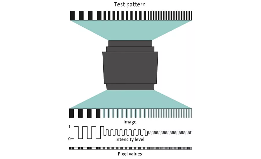
Figure 1. Modulation transfer function
The cameras, lenses and illumination used in a machine vision system all make significant contributions to the overall quality of the images that are produced. The rapid developments in CMOS image sensor technology over the last few years have created significant challenges for lens manufacturers. The move towards higher and higher sensor resolutions means that there are now many sensors with much smaller pixels, requiring higher resolution lenses. On the other hand, higher resolution sensors that maintain larger pixel sizes for higher sensitivity are often larger format and so will require larger format high resolution lenses. In addition, many applications that require lenses with very long focal lengths such as surveillance, sports, aerial photography, and photography on theme park rides are increasingly coming under the umbrella of machine vision and need to be addressed. A number of factors are important in lens design and these include lens resolution, spatial distortion and uniformity of illumination through the lens.
Understanding lens performance - modulation transfer function (MTF)
The ideal lens would produce an image which perfectly matches the object, including all of its details and brightness variations. In practice this is never completely possible as lenses act as low pass filters. The image quality of a lens, taking into consideration all aberrations, can be described quantitatively by its modulation transfer function. MTF is defined by the ability of a lens to reproduce lines (grids) with different spacings (spatial frequency in line pairs/mm). The more line pairs/mm that can be distinguished, the better the resolution of the lens. The loss of contrast due to the lens is shown in the MTF-graph for each spatial frequency (Figure 1). Large structures, such as coarsely spaced lines, are generally transferred with relatively good contrast. Smaller structures, such as finely spaced lines, are transferred with low contrast. The amount of attenuation of any given frequency or detail is classified in terms of MTF and this gives an indication of the transfer efficiency of the lens. For any lens there is a point at which the modulation is zero. This limit is often called the resolution limit and is usually quoted in line pairs per millimeter (lp/mm), or with some macro lenses in terms of the minimum line size in µm which also equates to the minimum pixel size for which the lens is suitable. The MTF deteriorates moving from the center axis of the lens towards the edges, which is an important consideration if the nominal resolution is required across the entire image. MTF can also vary depending on the direction of the lines at a point on the lens due to astigmatism and is also a function of the aperture setting at which it is measured, so care must be taken when comparing lens performance. Since a lens must be chosen so that the resolving power fits with the pixel size of the image sensor, the smaller the pixels, the higher the resolution required from the lens.
Top Tip: Increasing sensor resolutions while maintaining the sensor size to keep costs down requires lenses with a higher MTF to resolve these smaller pixels. One should always consider the system cost as lower cost smaller pixel sizes demand higher resolution lenses.
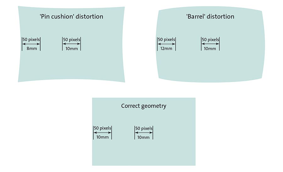
Figure 2. Spatial distortion
Spatial distortion
In addition to variations in resolution, all lenses also suffer from a certain amount of spatial distortion. Figure 2 shows how an image can be either stretched or compressed in a nonlinear way, making accurate measurements across the entire sensor very difficult. Although there are software methods available to correct this, they cannot take the physical depth of the object into account and it is always preferable to choose a good quality low distortion lens rather than attempt to correct these errors in software. As a general rule, a shorter focal length lens will have significantly more distortion than one with a longer focal length, as the light hits the sensor from a bigger angle. Using a more complex lens design, it is possible to keep distortion low and many lens manufacturers have been working hard on their optical designs allowing them to reduce spatial distortion to the order of 0.1%.
Top Tip: To minimize distortion at minimum cost, longer working distances will give the best results.
Illumination uniformity
All images from lenses suffer from vignetting, which is a decrease in illumination intensity from the center to the edge of the image and this can affect the suitability of a lens for an application. Mechanical vignetting occurs when shading towards the edges of the image results from the light beam being mechanically blocked, usually by the lens mount. This occurs mainly when the image circle (or format) of the lens is too small for the size of the sensor. All lenses are also influenced by ‘Cos4 vignetting’ which is caused by the fact that the light has to travel a further distance to the edge of the image and reaches the sensor at a shallow angle. This is also exaggerated on lenses with micro lenses on top of each pixel as the angle focuses the light in to a nonsensitive part of the sensor. This can be minimized if the lens is stopped down by two f-stops. By improving illumination uniformity across the entire sensor, lens manufacturers can eliminate the need for light intensity compensation, which could introduce noise into the image.
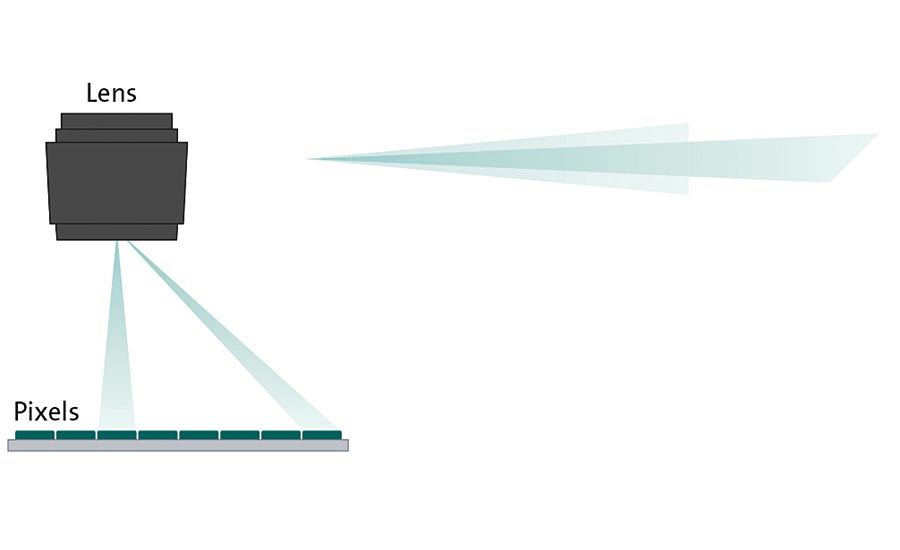
Figure 3. Mechanical vignetting
Environmental influences
Many vision systems are deployed in a manufacturing environment, which means that they are exposed to a variety of environmental influences, ranging from dirt, moisture and temperature to mechanical and electromagnetic effects. There are a number of protective enclosures available which can protect against the ingress of dirt and moisture. Mechanical stability of the lens assembly is of critical importance to avoid blurring and ensure robust and repeatable measurements. Most lenses used in machine vision applications are manufactured with metal housings and focus mechanisms to guarantee the stability of the lens. Many lenses are also available with anti-shock and vibration characteristics, making them suitable for even the harshest environments. Lens manufacturers have come up with a range of designs, a number of them patented, to limit the displacement of the image resulting from the lens glass shifting as a result of vibrations and impacts. These include the use of locking screws to prevent movement of focus and aperture, or even a fixed aperture, and the bonding of all of the elements in the lens body.
Lens mounts
Fixing a lens to a camera is achieved using one of a number of standardized lens mounts. The most commonly used in machine vision applications is the C-mount, which benefits from a very wide range of lenses and accessories including the ability to provide computer controlled iris and focus. A much less commonly used mount is the CS-mount. This is essentially the same as C-mount, but with a 5 mm shorter flange focal length. Smaller lens mount systems such as S-mount are normally used for board level cameras and micro head cameras. These lenses only allow a minimum of adjustment. For large format sensors and line scan applications, the larger format F-mount system can be used, although the more robust M42 mount (sometimes called T-mount), is used increasingly as an alternative. These large format lenses don’t support the capability of computer controlled iris and focus. One interesting development is the emergence of machine vision applications using lenses with very long focal lengths up to 600 mm. Developed for use mainly by professional photographers, these large format lenses also include motorized iris and focus. This requires the specialized EF lens mount, which incorporates these facilities. An increasing number of machine vision cameras are now being manufactured with EF mount capabilities and EF lenses with their novel optical capabilities being made available to the wider machine vision market through recent direct distribution agreements.
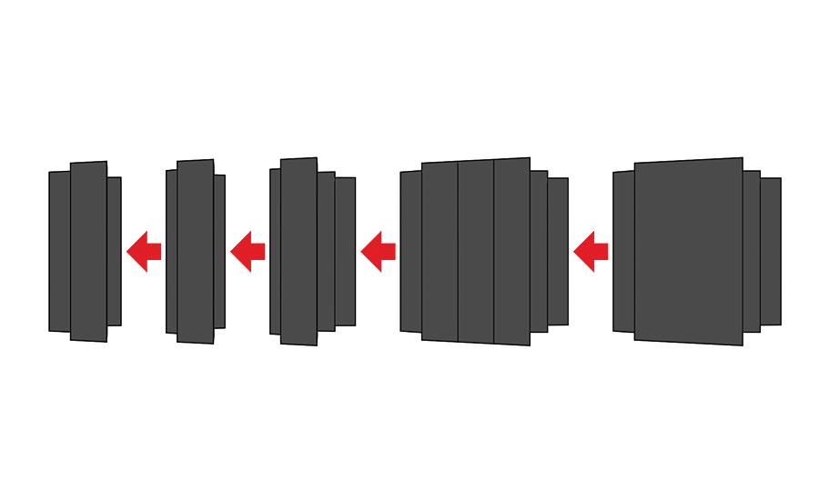
Figure 4. Different lens mounts
Getting it right
With so many machine vision lens options available, selecting the best one for the particular application may not be a trivial exercise. It is important to consider the system as a whole. For example, many modern megapixel cameras use small sensor sizes to reduce costs, but the resulting small pixel sizes require higher quality and therefore more expensive optics. For some applications it may be beneficial to choose a more expensive camera with larger pixels that requires less demanding optics to reduce the overall system cost. Working with expert vision technology suppliers can mitigate the risks in these decisions. V&S
Looking for a reprint of this article?
From high-res PDFs to custom plaques, order your copy today!


