Vision & Sensors | Machine Vision 101
Optics 101: Assembling a Machine Vision System
Defining the needs of the system will refine the choices for types of cameras, imaging lenses, and illumination schemes.
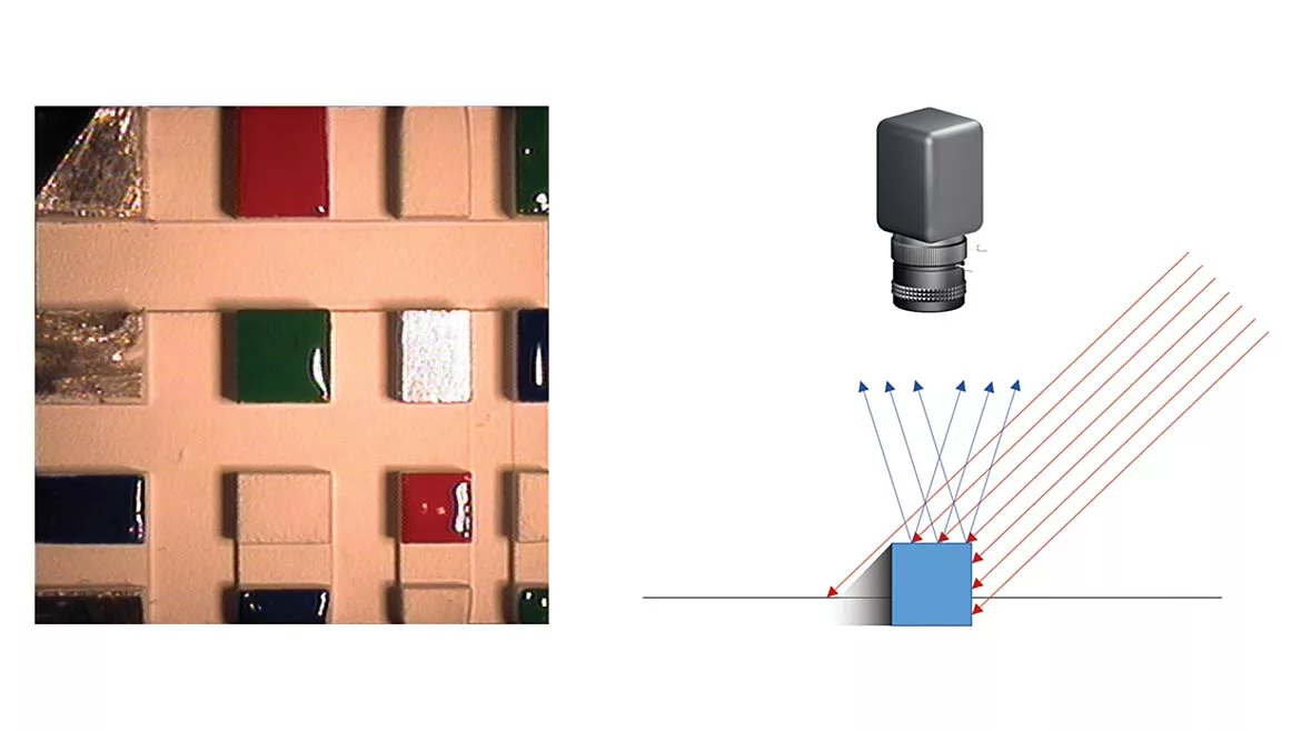
Image Source: Edmund Optics
Machine vision enables new and exciting advancements in industries and fields of research across multiple disciplines. Assembling a machine vision system can seem daunting, but the requirements of an application constrain an overtly wide selection of components: cameras, imaging lenses, and illumination sources, to a much more manageable selection of options. This resource provides an overview of the different aspects of a machine vision system with the goal of aiding in the component selection process.
Cameras
The sensor in a machine vision camera is the piece of technology that creates an image from the corresponding object in the field of view (FOV). The sensor is the part of the camera with the most specifications and dictates some of the most important characteristics of the camera. These important characteristics include but are not limited to sensor size, pixel size, spectral properties, and shutter type. Because of the wide variety of camera models suited for different purposes, applications, and technologies, it is important to understand the application in which the camera will be used.
The most common cameras interfaces are Universal Serial Bus (USB) and Gigabit Ethernet (GigE) and these interfaces provide standardized data transfer protocols and software compatibility. Additionally, camera interfaces determine specifications including data transfer speed and camera synchronization. USB 3.1 Gen 1 is a common interface with data transfer rates limited to around 5 Gb/s. GigE connections range from 1000 Mb/s to 10 Gb/s. Data transfer speed affects frame rate. For objects that move quickly through the FOV, the faster data transfer rate associated with a GigE interface may be a better choice than a USB interface, especially for real-time video capture. Typically, USBs supply power to the camera. By default, most GigE interfaces do not supply power to the camera. However, some GigE interfaces can make use of Power over Ethernet (PoE) or Input/Output connections (GPIO). These PoE and GPIO interfaces will require extra cabling and power supplies.
Sensor size determines the size of the FOV and the primary magnification (PMAG) of the system. Figure 1 shows the naming convention used for sensor formats, which is based on obsolete cathode ray video camera tubes for television cameras used from the 1930s to the 1990s. The naming convention, which has numerals, does not provide direct information about the sensor dimensions of which they refer. However, maximum sensor format is specified for imaging lenses on specification sheets. If a camera sensor is larger than the maximum sensor format for the lens, darkening around the edges of the sensor occurs; this phenomenon is called vignetting. Sensor size compatibility is important to keep in mind when selecting an imaging lens.
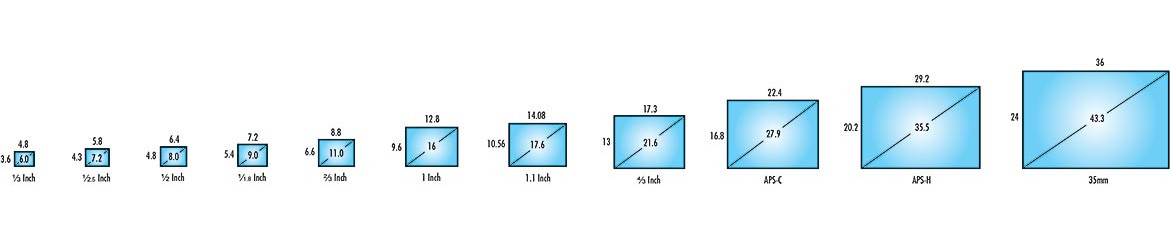
Figure 1: Sensor size formats for standard machine vision camera sensors. Image Source: Edmund Optics (Click on the image to enlarge.)
There are two types of sensor technologies mainly used in machine vision cameras. Charged coupled devices (CCDs) and complementary metal-oxide-semiconductor (CMOS) sensors, both of which convert light into electronic signal. In a CCD sensor, each pixel’s charge is converted to a voltage, buffered, and transferred through an analog signal. CMOS sensors convert light to electronic signals at the pixel level. Recent advances in CMOS sensors allow for pixel uniformity within conversion and enable CMOS sensors to perform to similar standards as CCD sensors and in recent cases, outperform CCDs. CMOS sensors offer decreased power consumption, which is preferable for space-constrained applications. Square-shaped pixels capture light on the sensor grid. Pixel size determines camera resolution, or, more accurately, the minimum distinguishable feature size of an object, which is related to but slightly different than resolution. Smaller pixel size increases resolution. To image continually finer details requires higher resolutions.
The spectral properties of a camera sensor can be used to refine camera options from the selection process. A color application will eliminate monochrome models because monochrome cameras only produce grayscale images. A monochrome camera will also offer increased resolution performance than color cameras due to the way pixels are arranged on a sensor for color sensors. A single-chip color camera uses an RGB Bayer Color Filter to reconstruct color images. Four singular pixels in a color camera capture the same area as a single pixel in a monochrome camera.
Frame rate is also important to define early in the selection process. Capturing a product moving down a conveyor line requires higher frame rates than for a stationary object. Frame rate is defined as the number of full frames composed in a second. Cameras can run at a higher frame rates by reducing resolution or specifying an area of interest (AOI) within the maximum achievable sized FOV, but doing so reduces image quality.
A final consideration for cameras is shutter speed. The camera shutter controls exposure time, which is used to capture pixel contents and then create an image. There are two different standard types of camera shutters: global and rolling. A global shutter exposes and samples pixels simultaneously and pixel readout occurs sequentially. Rolling shutters expose, sample, and then read out sequentially. Thus, each line of pixels is sampled at slightly different times. With a global shutter, a moving object’s image can be distorted and blurred. If the object is moving, a rolling shutter could be considered to prevent distortions. Figure 2 shows the difference in the image captured with these two shutters.
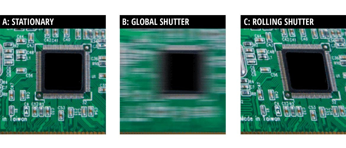
Figure 2: A motion blur comparison showing a stationary object (A), a moving object with continuous global shutter (B), and rolling shutter (C). Image Source: Edmund Optics (Click on the image to enlarge.)
Lenses
A machine vision camera cannot produce a clear image without a lens. There are different types of lenses including fixed focal length, telecentric, and many other specialty lenses. Each type of lens is optimized for a specific application. The table below lists parameters used to define an imaging system.
A fixed focal length lens has a fixed angular field of view (AFOV) which defines the image circle. For a given sensor size, shorter focal lengths create wider AFOVs. If the object is stationary, or if the depth of field is not changing, then a fixed focal length lens is sufficient. Additionally, telecentric lenses yield a constant magnification over a range of working distances, eliminating viewing angle error. The images created by telecentric lenses eliminate height variations within objects, which is useful for applications that require dimensionally accurate images. Below in Figure 3, images created by a fixed focal length lens and a telecentric lens are compared.
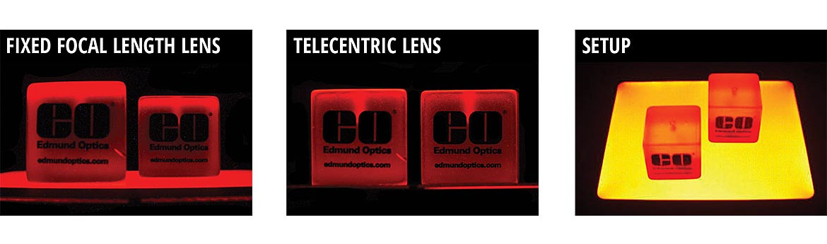
Figure 3: The images created by a fixed focal length lens and a telecentric lens. Image Source: Edmund Optics (Click on the image to enlarge.)
A number of different types of specialty lenses accommodate a variety of more niche applications. A zoom lenses is a lens with a range of focal lengths. There is a loss in the maximum achievable resolution associated with the design of zoom lenses. This loss is a physical limitation that comes with an increase in flexibility in focal length options. If an application requires an actively changing FOV, then a zoom lens is a great option. Microscope objectives are also available for imaging very small objects. There are multiple different types of objectives summarized in Table 2 below. Objectives offer high magnifications, typically between 1x to 100x and allow imaging of fine details. Objectives also have smaller FOVs in comparison to typical imaging lenses. Microscope systems offer compatibility with machine vision cameras, and some objectives have thread adapters for direct camera mounting. There are many different lens types, but by defining the size of an object that requires imaging and the distance at which it is being placed, the best imaging lens can be selected.
Table 2: Common Types of Illumination Recommendations for an Imaging System

Table 2A directional
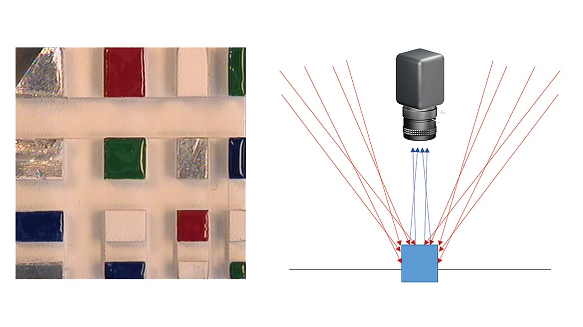
Table 2B diffuse
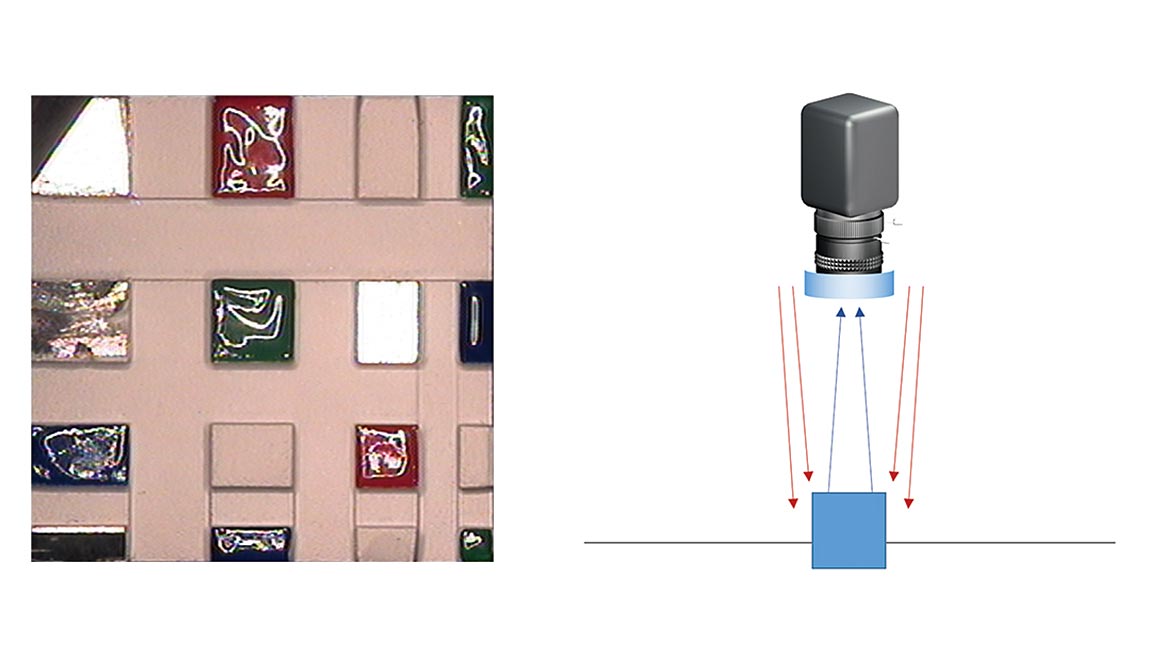
Table 2C ring
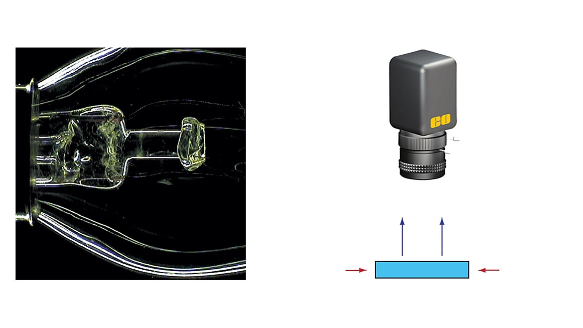
Table 2D Darkfield
Talble 2E bright. All Images Source: Edmund Optics (Click on an image to enlarge.)
Illumination
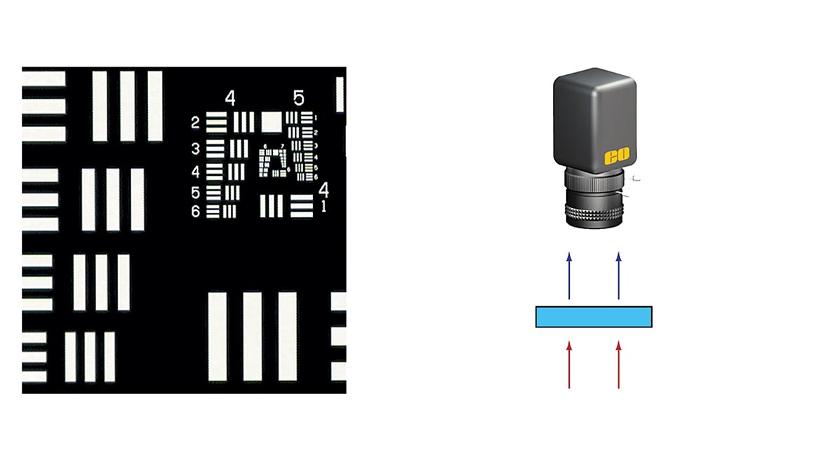
The last important and major set of characteristics for an imaging system is related to the illumination. If the environment is too dark, a clear image is nearly impossible. Many fixed focal length lenses have adjustable apertures. The f-number (f/#) is a value that describes the size of the aperture stop, which is the point along the optical axis and within the lens stack, where the cross-sectional area that light passes through is the smallest. A larger f/# is associated with an increase in aperture closure and less light entering. External apertures can also be used to control light throughput if a lens does not have an internal aperture. Machine vision filters may be used to reject or pass certain wavelengths or wavebands into or out of the imaging system. Polarizers can also be used to pass or reject specific polarizations of light to eliminate glare for clearer pictures. Figure 4 shows the difference between images with polarized and non-polarized light.
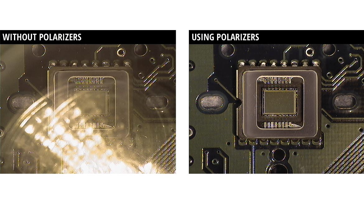
Figure 4: The effect of polarization on image quality. Image Source: Edmund Optics (Click on the image to enlarge.)
There are multiple types of illumination that can be accomplished with different sources. LEDs offer long lifetimes, are available in a variety of colors, and can be intensity controlled for specific configuration of many illumination schemes. Fiber optic illumination typically uses light guides to direct light into specific space-constrained applications. Light guides are used for in-line illumination, which is integrated into many telecentric lens designs. In-line illumination enables brightfield illumination over the entire FOV. Figure 5 shows the difference between using a telecentric lens with a ring light versus in-line illumination. The image shows a divergence of the beam path between both types of illumination. By determining the ideal type of illumination for the application, blurriness is minimized and image quality is improved. Table 2 defines different types of illumination and shows how the illumination is used. The object surface and surrounding environment help determine what type of illumination is needed for the application requirements.
Overall, an imaging system is defined by asking questions about the specific application requirements. Defining the needs of the system will refine the choices for types of cameras, imaging lenses, and illumination schemes.
Looking for a reprint of this article?
From high-res PDFs to custom plaques, order your copy today!


