Measurement
Best Suited Options for Your Metrology Toolbox
When are non-contact structured light 3D scanners better suited than touch CMMs?
All Images Source: Capture3D, a Zeiss Company
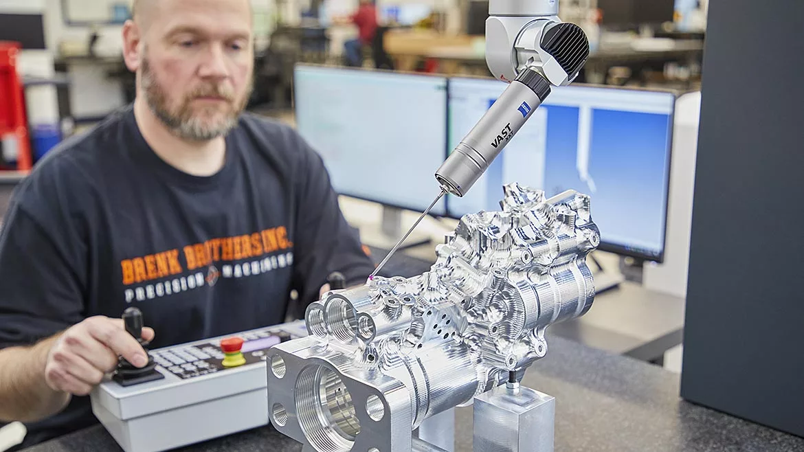
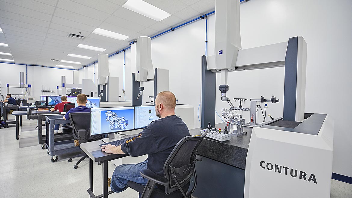
For measurement, testing and inspection in plastics processing, there are many technologies that make up the modern metrology toolbox. Each technology has its own features, characteristics, and strengths. For example, tactile coordinate measuring machines (CMMs) have long been a dependable and repeatable method of collecting accurate measurements where the probe touches the object's surface to gather data. A full range of accuracies are available in CMMs with several providing submicron accuracy. Non-contact optical structured light 3D scanners are another option that provide fast and accurate 3D digitalization of the entire object. The accuracy of structured light 3D scanners can also range, but single-digit one-to-two-micron accuracy can be achieved with smaller measuring volumes. The science behind the technologies is different; however, both collect coordinate measurement data and are widely used within the plastics industry. The question of when to consider using structured light 3D scanning is addressed by considering the application, its challenges and the required outcome.
Though contact metrology is the traditional methodology used for measurement, structured light 3D scanners also work in conjunction with tactile CMMs as a complementary enhancement in this process because of the 3D digitalization capabilities they provide to resolve common challenges plastics manufacturers face. Some of these challenges include increasing throughput, overcoming blind spots in data analysis, reducing the number of correction loops, lack of skilled workers, managing costs and materials in a tightened supply chain, controlling process variations, and monitoring the health of tooling to avoid unplanned downtime. For example, an automotive plastics tier-one supplier increased the number of parts scanned per year by more than 20 times after implementing structured light 3D scanning. Another automotive original equipment manufacturer (OEM) of air filter components reduced tool tuning iterations of plastic injection molding parts from 3-4 to 1-2 using structured light 3D scanning technology.
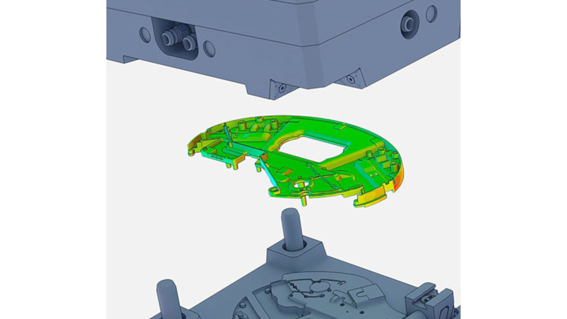
One type of structured light 3D scanner is ATOS which stands for "Advanced Topometric Optical Sensor." ATOS is an optical 3D coordinate measuring system that captures millions of X-Y-Z coordinate points per scan, making up the complete surface geometry of prototypes, electrodes, tools and injection molded parts of any size. This complete data capture, also known as full-field data, happens without programming or touching the part, making it an easy-to-use technology for collecting measurement data from parts with complex freeform contours or organic shapes. Utilizing data from this structured light 3D scanner in the ATOS GOM Software provides opportunities to apply digitalization to optimize the various phases of plastics engineering, from prototype and tool construction to mold flow analysis, first article inspection reports, assembly analysis, and trend/SPC analysis. The resulting digital twin of the tooling and parts provides insights into process performance and historical data for lessons learned and archiving.
Digitalization with full-field data resolves many challenges throughout plastics processing:
Controlling Variations With PMI/MBD And Advanced CAD Modeling In The Design Process
Using an annotated 3D model containing semantic product manufacturing information (PMI) data in a process known as model-based definition (MBD) accelerates new product development and production process planning by providing key information that ensures all stakeholders within the manufacturing process are informed. In addition, 3D measurement and inspection planning can take place directly on a computer-aided design (CAD) model containing the required dimensional features. Designating a company-specific set of measurement criteria, including geometric dimensioning and tolerancing (GD&T) and other tolerance specifications, before component production begins provides a single source of truth from the beginning, supporting process control and fostering better communication throughout all downstream processes. By importing the PMI data in GOM Software and comparing it to the actual data from an ATOS structured light 3D scanner, it enables real-time visualization and dimensional analysis of the entire object to reveal the problematic areas quickly. This in-depth analysis also helps plastics manufacturers determine whether a tooling correction is necessary.
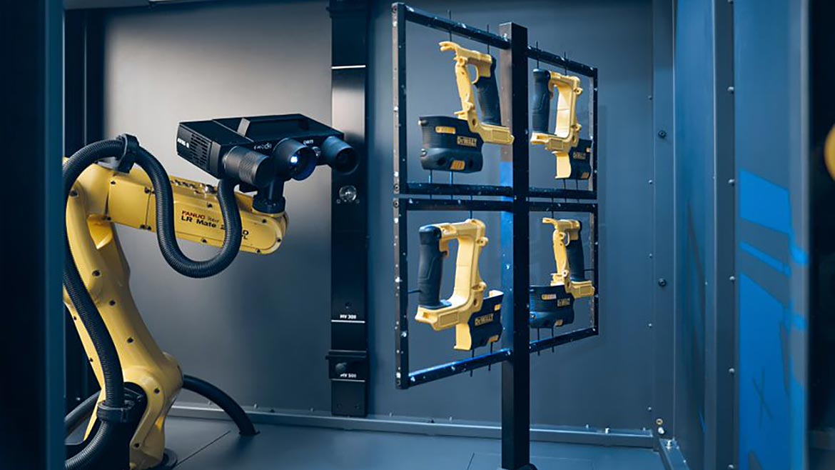
With automated blue light 3D scanning, companies measure multiple parts simultaneously to increase throughput and repeatability in the measurement and evaluation process.
Managing Costs And Materials With Accurate Simulation And Verification
With a digital twin comprised of accurate 3D scan data, mold filling, sprue, holding pressure, temperature control and filling time of injection-molded parts can be computed and visualized digitally to prevent errors and optimize the use of materials, cycle time and machine size through simulation. By prognosticating the material behavior and process parameters, plastics manufacturers can overcome significant challenges, such as managing the costs of materials and controlling processes by making necessary modifications to them before they are implemented.
For example, mold flow simulation and analysis are more reliable when performed with an accurate digital twin of the physical mold. Furthermore, the scanned data provides actionable insights by allowing plastics processors to quickly see where to adjust the mold accordingly.
With accurate full-field 3D data, injection molding simulations can be verified, increasing the reliability of numerical simulations and contributing to optimizing process parameters. Comparing simulated and real components and evaluating the trend analysis from simulated parameters supports more reliable decisions on process optimization.
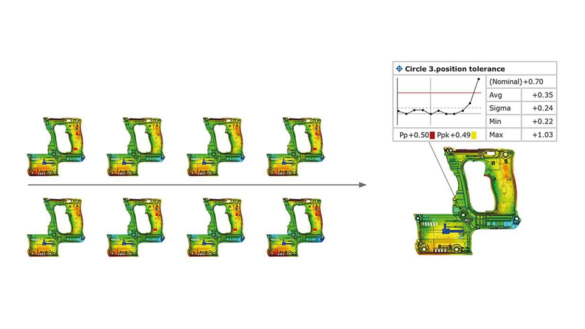
Plastics manufacturers can use accurate 3D scan data from ATOS 3D scanners to avoid unplanned downtime proactively by using trend analysis to monitor when deviations begin to reach a specified tolerance.
Understanding How Components Fit Together With Virtual Assembly
Another form of simulation digitalization enables is virtual assembly analysis. Plastics manufacturers can use digital twins of physical parts to conserve material costs by testing and verifying form, fit and function in a digitized environment before sending parts into production. Inspecting how components fit together and matting surfaces also reveals issues earlier in the process. For plastics manufacturers working with employees, OEMs, suppliers and other stakeholders in remote locations, the ability to collaborate and share this analysis ensures the parts will fit and function when brought together in the physical world. Implementing process control at an early stage reduces correction loops, especially for components with multiple cavities. For example, in the tryout phase, analysis of 3D measurement data reveals where specific tool corrections are needed, resulting in a lower material input and reduced waste.
A full range of accuracies are available in CMMs, with several providing submicron accuracy.
Overcoming Warpage And Shrinkage
Warpage and shrinkage are among the most common issues for plastics manufacturers. The goal of producing a part near net shape molding presents challenges. Due to the materials and process, the required shape of the injection parts creates visible deformations known as warpage and shrinkage. Warpage, often occurring during the cooling process, is when the part's shape is distorted and has a slight twist, bend, or bow. Shrinkage is when the part contracts in size during the cooling process. Other factors such as stress during demolding and the use of glass-reinforced plastic molding, large surface areas, or thin, weak parts also impact the structural geometry of plastic parts.
Digitalization using 3D scanning allows the analysis of plastics in a simulated environment, a critical advantage for plastics manufacturers who struggle with materials prone to warpage and shrinkage. For example, plastics manufacturers can overcome these deformations using ATOS full-field 3D measurement data inside GOM Software. The De-Warp software module uses algorithms for the virtual compensation of warpage and shrinkage, making it possible to detect over-constrained datum conditions without mechanical fixtures.
This technology uses the calculations of deformation models as the basis for virtual clamping, simulating the application of a virtual force onto the part by defining several clamping points, effectively transferring the digitized part into a clamped state for measurement and analysis. The measurement result can be switched between a clamped and unclamped state in a full-field scan data comparison with the CAD model without physically clamping the part. Then, a newly compensated file is produced to manufacture near net shape.
Plastics manufacturers can use digital twins of physical parts to conserve material costs by testing and verifying form, fit and function in a digitized environment before sending parts into production.
Regulating And Monitoring The Health Of Tooling To Optimize Processes And Avoid Unplanned Downtime
Plastics manufacturers use 3D scan data to avoid unplanned downtime proactively by using trend analysis to monitor when deviations begin to reach a specified tolerance. Comparing 3D scan data of how the actual manufactured part wears over time delivers insight into the health of the tooling. By examining the entire geometry, plastics manufacturers clearly understand areas to adjust, correct and improve.
Additionally, using complete full-field 3D data in mold validation quickly delivers reliable warpage and deformation measurements of plastic parts, providing insights that lead to targeted tool optimization and process correction. Retaining the digital twin resulting from structured light 3D scanning enables quick comparisons of the part's condition throughout its lifecycle to achieve optimal quality control. Archiving this data makes it accessible to have a digital file of the final tooling after the rework and modified shape.
GOM Software's GD&T functions can perform GD&T checks on any area of a digitized component.
Eliminating Blind Spots In Data Analysis With Full-Field Data Collection
The output of a 3D scanner is an STL point cloud file that can be exported into other file types. While the overall point cloud size is not a critical factor for successfully measuring your parts, a more significant factor is the spacing of the points (point spacing) within the point cloud. Structured light 3D scanning uses volume-based measurement to collect an area of a surface from 100mm to 1000mm, capturing millions of points in one scan. For example, ATOS 5 has dual 12-megapixel high-resolution cameras, equating up to 12 million points per scan. The intelligent algorithm analyzes the geometry to use a higher point density on intricate features, resulting in the accurate measurement of critical areas. The determination of the measurement volume size is based on part geometries, tolerances, and overall size of the part.
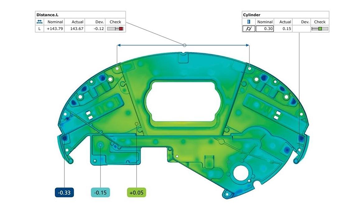
The point cloud depicts an overall 3D blueprint of the actual part's geometry and is used widely for dimensional analysis. By comparing the actual 3D scan data to CAD or even part-to-part, the software provides immediate data visualization using color maps for immediate feedback. This in-depth analysis quickly reveals where the object is in or out of tolerance.
Dimensional analysis using full-field data allows for comprehensive analysis. For example, if flatness needs to be checked, 3D metrology software functions can perform GD&T checks on any area of the component.
Another common concern facing plastics manufacturers is verifying that a part's structural integrity is designed with the right amount of material to be geometrically sound and optimized for weight while also considering the manufactured part's stress, fatigue, and assembly condition. Traditionally, plastics manufacturers use an engineering calculation called material thickness to determine the integrity of the wall structure. However, in GOM Software, material thickness can be calculated accurately using 3D scan data from the actual part, in addition to further analysis of gate designs, pins, undercuts, sink marks, surface defects, and more.
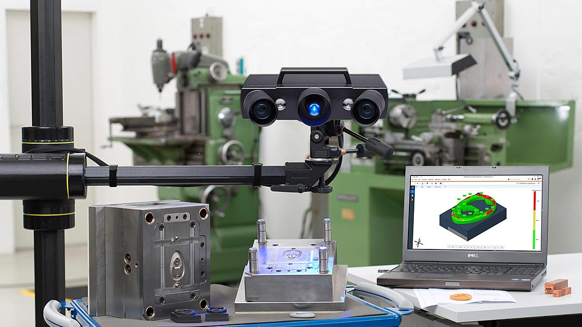
ATOS blue light 3D scanning expands measurement and inspection capabilities for plastics manufacturers by collecting accurate 3D data that provides actionable insights
Increasing Throughput With Automated Quality Control
Automating the measurement and evaluation process is the most effective method of increasing throughput, repeatability, and production-accompanying quality control speed. ATOS ScanBox series offers robotic integration with advanced safety and software for easy-to-use operation. Companies measure multiple parts simultaneously or use the ScanBox BPS solution, which provides an automatic part handling system to intelligently inspect batches of parts. Repeatable inspections reduce operator errors and increase efficiency. Companies have experienced more than a 70% increase in throughput by integrating automation into their plastics manufacturing processes.
Manufacturers often hesitate to implement automation, believing they will need to employ a robotics expert. However, GOM Software offers a solution that allows automatic offline and online programming, including the kinematics of the robot paths and inspection planning to occur safely in a simulated and controlled environment, called a Virtual Measuring Room (VMR), requiring no specialized robotics training to operate. With Smart Teach, the software automatically calculates the robot's position by the CAD file and further optimizes its path to ensure efficiency. After the optimal robotic measurement paths are determined and verified within the software, inspection occurs.
Resolving Lack Of Skilled Workers With Easy To Operate Technology And Easy To Read Inspection Reports
Implementing technology that requires little training to operate helps alleviate the strain on plastics manufacturers struggling to find skilled workers. Using digital engineering techniques like MBD/PMI to plan inspection and communicate measurement criteria removes the guesswork, garnering consistent and repeatable results without specialized training. With inspection reports containing visual 3D data, results are understood and communicated quickly, allowing more employees to contribute to determining corrective action.
Each Technology Has Its Place In Plastics Processing
Structured light 3D scanning is a rapidly developing technology, and plastics processors have realized the benefits that stepping into the 3D digitalization enables by combining traditional and modern methodologies into their processes. While tactile CMMs are more commonly used for measurement in plastics processing, structured light 3D scanning complements that ability with digitalization that resolves challenges across many diverse industries, from automotive to aerospace to consumer goods. Since CMM costs can be relatively the same when compared to structured light 3D scanning, depending on additional variables like automation, cost should not necessarily be a deciding factor of which technology to use, but rather, consider the application at hand, the required results and the challenges along the way to getting there.
Looking for a reprint of this article?
From high-res PDFs to custom plaques, order your copy today!


