More than Laser Gages - Available Today
The added twist in recent years has been the use of a chromatic or "color" focus effect where different colors of light focus at different distances.
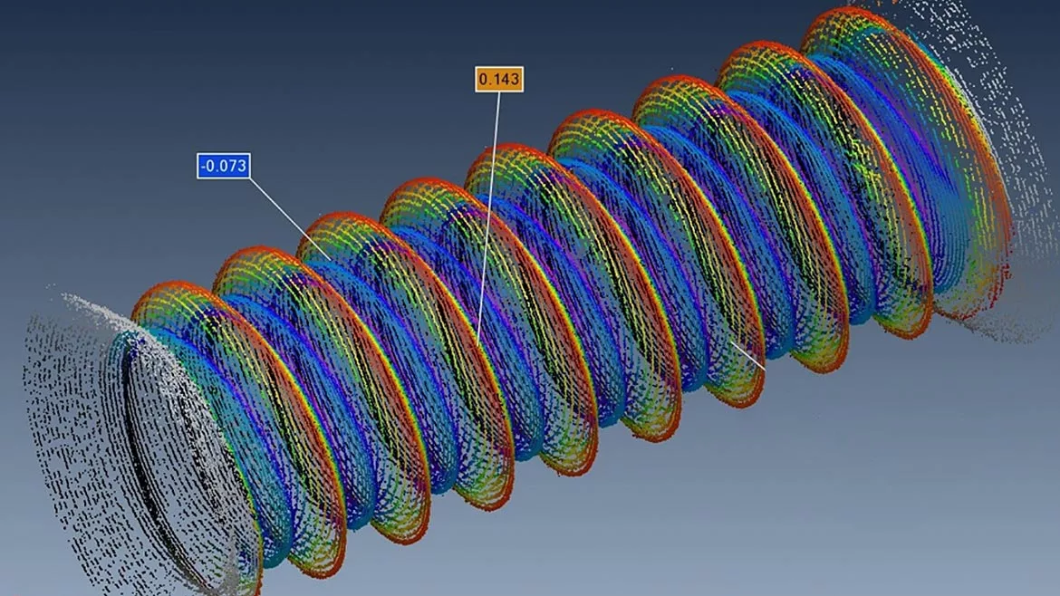
Image Source: Novacam
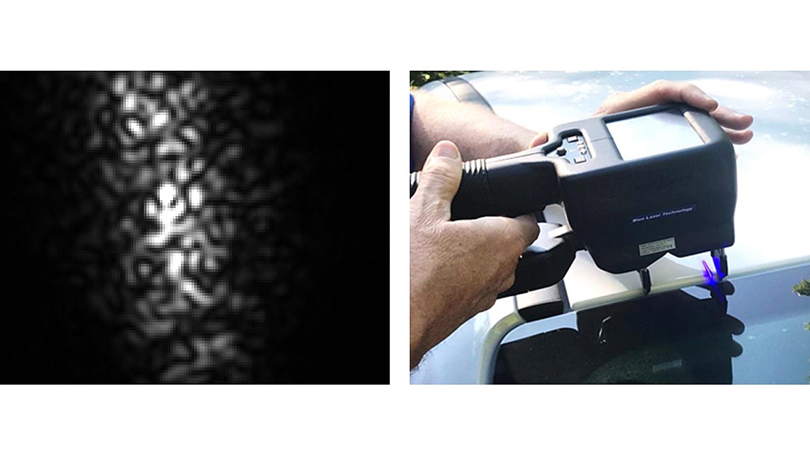
Laser based triangulation gages have been around and in wide use for over 50 years with many users viewing them as commodity items. Rolling mills use laser gages to check the flatness of rolled sheet metal, foundries use them to measure the height of molten metal, and car manufacturers use them to check fit and finish of cars. Prices have come down over the years and capabilities have improved. Making measurements to a thousandth of an inch over several inches of range can be had for a few hundred dollars with long range and highly ruggedized sensors costing just a bit more. These sensors offer high reliability and robustness, but with some lingering issues such as the “laser speckle” noise seen on rough surfaces and variable textures that still pose some challenges.
Over the past 10 to 20 years, new optical sensors have been introduced on the market that offer new capabilities such as submicron capabilities for small precision parts measurement as well as on-line surface measurement capabilities, formerly only possible with precision stylus instruments not really compatible with the in-process manufacturing environment. These newer tools include:
- focus based measurements such as depth-from-focus or defocus systems,
- confocal methods with added range from chromatic focusing effects,
- white light interferometry methods, originally developed around biological mapping needs such as cancer screening.
There are multiple suppliers of these tools and of course, there are always new variations being developed. In this article, we will examine how these new optical sensors work and how they might be used to address critical needs for part qualification and process control in precision manufacturing applications.
How They Work
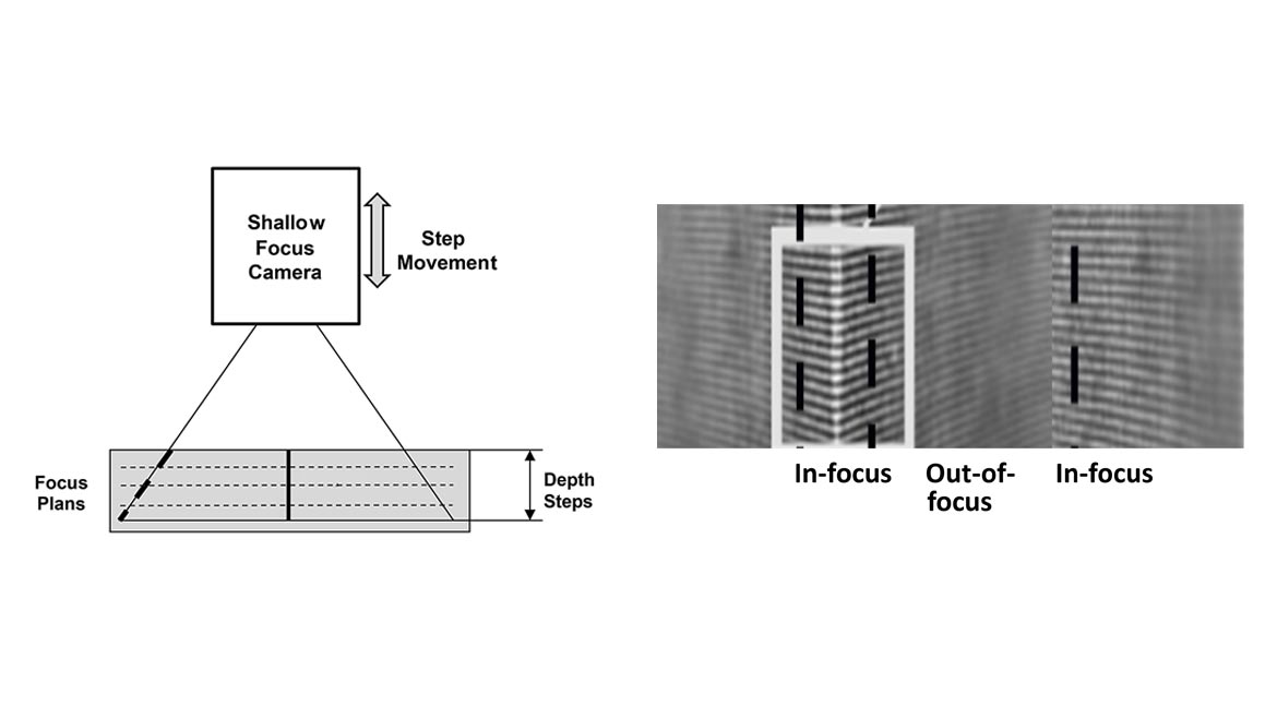
Depth-from-focus (DFF) uses an effect often seen in photography. A camera can obtain a sharp image at one distance but features closer or further away may be out of focus. By taking a larger number of images at different focus settings and searching the features by clarity for each focus setting, the user can build up a map of the range for each point in the image that is in sharp focus at some focal distance. [1] Some microscope systems use this approach to define regions within each image that are in best focused and then combines those regions to build up a single, in-focus image. One application of this tool has been in the inspection of integrated circuit boards to verify part and solder placement.
A different way to look at focus clarity from using only what is in-focus is to use a model of the optical imaging and the amount of defocus blur at each point away from any focus plain to estimate how far a particular image feature is from a best focus image. Depth-from-defocus has the potential to create a continuous map of all range points on a subject, with many fewer image planes than depth-from-focus methods.
The assumption of something to focus upon wherever you measure still must be satisfied for both these approaches. But rather than interpolating between best focus image range points using depth-from-focus, the amount and nature of the defocus of edges and features can be used to determine the range at each feature analytically.
Both of these methods have been used for mapping small parts such as electronics, cutting tool mapping and screw threads as well as to some extent, measuring the surface finish of machined metal parts. The limit on measuring surface finish with focus-based methods is reached when the texture is below the optical resolution of the lens, which for a small field of a few tenths of an inch (few millimeters) might be 20 millionths of an inch (0.5 microns). Below some practical level, the optical method cannot see anything to focus upon. But for surfaces that are measurable, a measurement in a few seconds can be had over parts and areas of a few inches and sub-tenth of a mil (1-2 micron) levels.
Confocal methods have been around for a long time for use in biology to measure cell structure. The old confocal microscopes were strictly lab instruments that work much like the depth from focus method, but with an extra twist in the form of an optical filter which simply blocks any light from any point that is not in focus. These are typically point based measurements rather than area measurement as above but are also available as line measurement. The added twist in recent years has been the use of a chromatic or “color” focus effect where different colors of light focus at different distances. [2] In this manner, a color sorting device (such as a spectrometer) can quickly determine the range of each point without the need for mechanically scanning the sensor in depth as the older confocal design operated. This allows for faster measurements (thousands of points per second) within a working range than can be a fraction of an inch to inches in depth (few millimeters to centimeters).
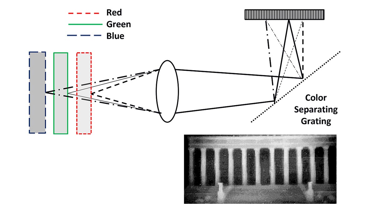
The inherent assumption for chromatic confocal sensors is that each color has a shallow focus depth and enough light is returned to detect it. In optics, a shallow focus depth means collecting and wide cone angle of light, either by being close to the part or having a large lens further away. This need for a wide cone of light also means that a larger surface angle (slope) relative to the sensor axis is going to degrade the measurement performance as light no longer fills the larger collection cone.
Chromatic confocal sensors have been effective at continuous fast scans (several kilohertz) across surface shapes with resolutions from thousandths to tens of thousandths of an inch (tens of microns to sub-micron). This has permitted faster scanning than is possible with a contract point or drag probe but with comparable resolutions.
The other measurement tool we will discuss is based upon the use of white light interferometry. Interferometry has been around for over 150 years as a means to measure optical elements that are made to millionth of an inch (nanometer) surface figures. These precision shapes allow us to make lab instruments like microscopes but also big telescopes like the James Webb Space Telescope recently launched. Some 25 years ago, a group of researchers at MIT used the effect that white light (non-laser or one color) will create an interference pattern over only a very shallow range on the micron to submicron scale.[3] Over time, similar tools as described above using mechanical scanning and spectral effects have led to the benchtop white light interferometers often seen in precision manufacturing shops today as a standard for measuring surface finish or fine features like surface defects. A similar scanning mechanism is typically used in these instruments but now using the presence of an interference pattern of “blinking light” to identify specific locations at a given depth rather than focus clarity. More recently, these tools have been extended to point measurement sensors that can provide very fast sub tenth of a mil (sub-micron) level measurements at kilohertz rates. [4]
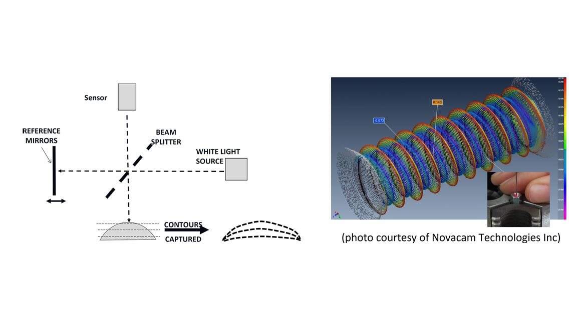
The white light interferometer sensor can have inches (centimeters) of range without the need for a large collection angle of light. Systems using mirrors and rotating scanners have been effective at measuring small, deep bore holes and cavities looking through limited size access ports. The light still needs to reflect back to the sensor, and it cannot be “scrambled” such as the light piping seen in a plastic or translucent part. But otherwise, the white light probe can provide a robust measurement at very fine dimensions.
Why Is This Useful?
These new variations of optical area, line and point probes compared to the old laser triangulation gage provide higher resolution measurements without the need for triangulation angle access to the surface and without the classic “laser speckle noise” that has limited the use of optical gages in the past. The ability to get into small holes and ports, see internal cavities and map over a step height change without shadows due to the triangulation angle needed, offers the potential to address applications that could not be easily done with classic laser gages.
Looking for a reprint of this article?
From high-res PDFs to custom plaques, order your copy today!


