NDT | Phased Array
Phased Array Ultrasonic Testing
Inspection reliability continues to improve thanks to the development of new imaging techniques like the total focusing method.

Image Source: Funtay / iStock / Getty Images Plus / via Getty Images
Phased array ultrasonic testing (PAUT) has been steadily supplanting conventional ultrasonic testing since its introduction in the early 2000s. PAUT offers significant advantages over conventional UT in terms of both data acquisition and data analysis. In addition, advances in PAUT hardware have led to the development of more advanced imaging techniques such as full matrix capture/total focusing method (FMC/TFM) which offer improved flaw sizing and characterization. This article gives a general overview of PAUT technology and details its benefits relative to conventional UT, followed by a brief discussion of the next generation of PAUT inspection technology: FMC/TFM.
Conventional Ultrasonic Testing
Ultrasonic testing (UT) uses high frequency mechanical waves to find flaws in industrial components. Flaws manifest as abrupt changes in material properties (stiffness and/or density) which reflect ultrasonic waves as they propagate through a test piece. UT is often used instead of radiographic testing (RT) as UT does not require the handling of radiographic materials and is more sensitive to common weld flaws such as cracks and lack of fusion.
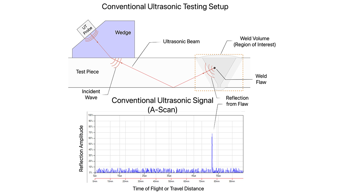
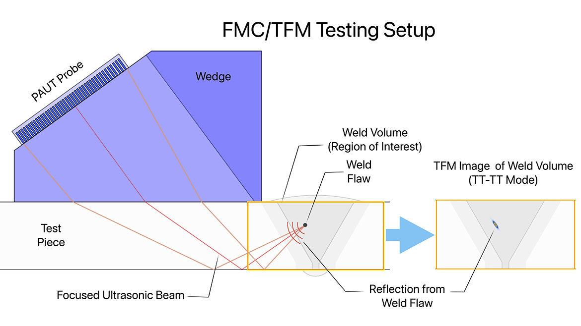
Using a special piezoelectric sensor or “probe”, a short ultrasonic pulse is launched into a test piece, often by using a refracting “wedge” to direct the beam towards the region of interest – see Figure 1 (top). When the incident beam interacts with a flaw, the resulting reflection travels back along the same path to the probe registering a signal, commonly referred to as an A-Scan - Figure 1 (bottom). An A-scan maps the strength of reflections detected by the probe (Amplitude) as a function of time elapsed from the time the pulse was sent by the probe, which can be related back to the position of the reflection in the piece.
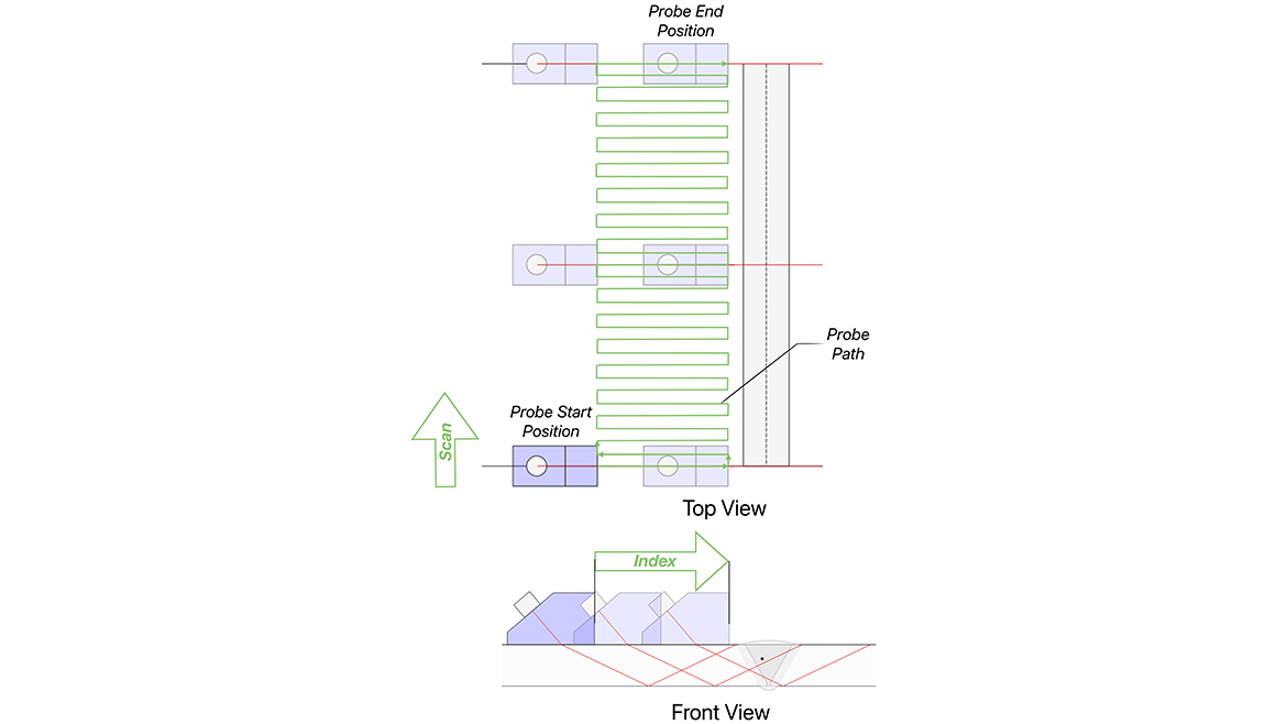
To cause a reflection that can be detected in the A-scan, the flaw must intersect the ultrasonic beam somewhere along its path through the piece. Since flaws can occur anywhere within the inspection volume, the probe/wedge must be indexed forward (or backwards) so that the beam path covers the entire region of interest – see the Front View in Figure 2. This indexing of the probe towards the weld must be repeated along the entire length of the component, as shown Figure 2 (Top View). Conventional UT inspection is typically performed manually, requiring the technician to simultaneously monitor the A-scan display on the UT instrument for flaw reflections while ensuring the probe/wedge follows the defined scan pattern. This process is further complicated by the fact that a layer of coupling gel or oil must be applied and re-applied to allow transmission of ultrasound into the piece. Together these challenges can lead to technicians failing to identify critical flaws and make the outcome of any inspection highly dependent on the diligence of individual inspection personnel. Since the probe is being manipulated by hand and the A-scans analyzed on the fly, there is also no way/need to record the inspection data. The resulting inspection record, then, is simply a report detailing the location of any flaws detected during the exam.
Phased Array Ultrasonic Testing
The conventional UT testing approach can be made more robust by performing an encoded scan, whereby A-scans are digitized and recorded at each scan position - the UT data can then be analyzed after acquisition, giving the inspector time to properly scrutinize the results without having to worry about manipulating the probe. Acquiring encoded scan data with a conventional UT probe wedge requires a robotic scanning system capable of physically indexing the probe to achieve coverage of region of interest – this approach is referred to as automated UT or AUT. Robotic scanning systems are costly and difficult to adapt to field conditions. Consequently, AUT has traditionally been deployed in production environments where the cost of the system could be justified by the volume of inspections e.g. inspecting new pipeline welds or performing corrosion surveys on large vessels.
NDT
A Quality Special Section
In the early 2000s, an alternative approach to acquiring encoded ultrasonic data was introduced. The technology, originally developed for diagnostic imaging, involves using an array of small ultrasonic sensors (elements) to shape and direct (steer) ultrasonic beams without having to physically reposition the probe. This is accomplished by pulsing the different elements at slightly different times such that the waves produced by individual elements constructively interfere to form a desired wavefront. The relative time shifting between the elements is called “Phasing” - accordingly, multi-element UT sensors arrays are called “phased array” probes and ultrasonic testing performed with these probes is commonly referred to as phased array ultrasonic testing (PAUT).
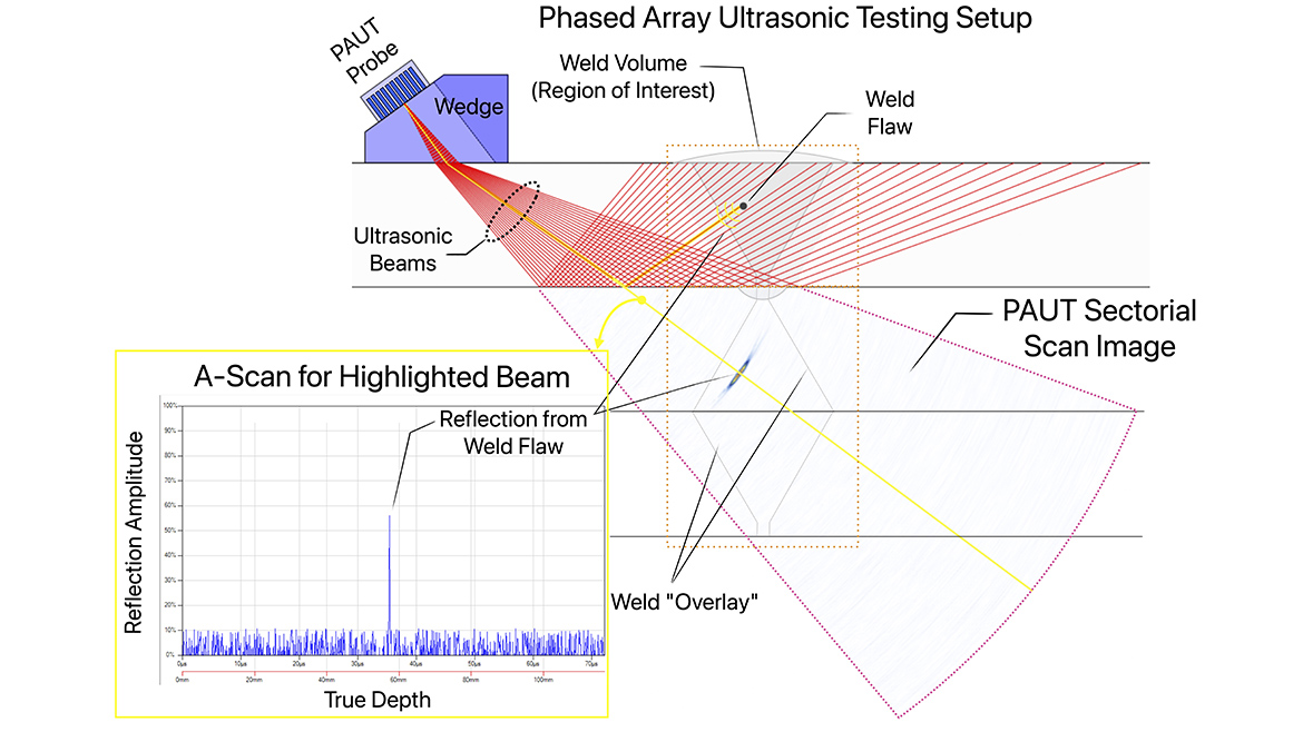
The main advantage of PAUT over conventional UT is that coverage of an inspection volume is achievable without having to physically index the probe, rather a PAUT probe can instead meet coverage by generating beams which refract at different angles – this is known as a “sectorial sweep or scan” and is shown in Figure 3. Each beam generated by the PAUT probe results in a single A-scan which can be viewed independently or stacked together in an image, where reflection amplitude is represented by a colormap – see Figure 3. Typically, the so-called “sectorial scan” image is plotted in unwrapped format with indications occurring after skipping from the component’s inner surface flipped vertically. The outline of the nominal weld geometry is often “overlaid” on top of the image to help the analyst make sense of the through wall position of reflections. The ability to observe A-scans from all beams covering the region of interest together as an image rather monitoring a single A-scan for anomalies while indexing makes it less likely that flaws will be missed by the inspector and allows for the through wall extent of any detected flaws to be estimated directly from the sectorial scan image.
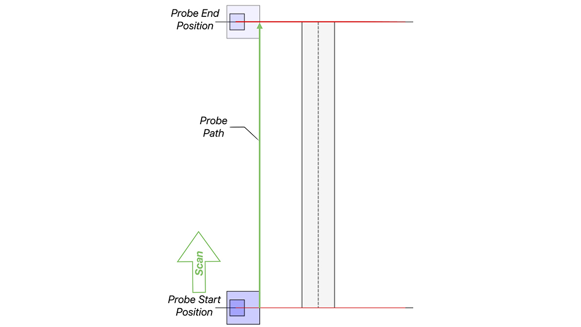
Another considerable advantage of PAUT over conventional UT is that acquiring encoded data does not, in general, require a robotic scanner - a PAUT probe needs only to be moved along the scan axis to cover the inspection volume which can be performed manually – see Figure 4. The position of the probe along the scan axis is readily tracked by a wheel(s) or drawstring attached to the probe which sends an electric pulse to the PAUT instrumentation telling it to fire the sequence of PAUT beams at predefined intervals (e.g. 1mm). The relative ease of acquiring encoded inspection data with PAUT means that PAUT scans are recorded and stored by default. Having digitized inspection data greatly facilitates the analysis process as technicians can view the UT results from the entire inspection volume by paging through sectorial scans or other projection views (B-scans/side views or C-scans/top views). Software tools that partially automate the analysis process according to code mandated detection criteria are becoming increasingly popular to ensure that all critical flaws are correctly identified, sized and positioned. From a quality perspective, having access to the inspection data makes it possible for regulatory authorities or client representatives to regularly audit the work of inspection companies without having access to components for re-scans.
Full Matrix Capture/Total Focusing Method: Next Generation Phased Array Inspection
Improvements in PAUT instrumentation have made more advanced imaging techniques practical to deploy. The most popular of these is a technique called full matrix capture/total focusing method (FMC/TFM) which is now available on most high end PAUT instruments. FMC/TFM uses the A-scans obtained by pulsing and receiving with all pairs of elements in a PAUT probe to generate a high resolution image of the inspection volume which is effectively “focused everywhere.” FMC/TFM images are more easily interpretable compared with PAUT sectorial scan images. Flaws are plotted true to geometry and their size and shape, texture etc., typically match the flaw much more closely than sectorial scan images which are entirely unfocused or focused at a specific distance with respect to the probe and out of focus elsewhere. As an example, the small weld flaw shown in Figure 1 and Figure 3 is imaged with FMC/TFM in Figure 4. Here the flaw indication is observed to look almost identical to the weld flaw itself (slag), especially compared with the sectorial scan image shown in Figure 3 where the target is considerably elongated. Having ultrasonic inspection data represented as high resolution images not only makes it easier for human analysts to detect, accurately size and characterize flaws, fully automated artificial intelligence based systems can be more straightforwardly trained using images as compared with A-scan signals or sectorial scan images.
Main Takeaways On Phased Array UT
- PAUT makes collection of encoded scan data feasible in nearly all circumstances.
- With PAUT, technicians do not need to analyze and scan simultaneously—flaws are less likely to be missed.
- Having access to digitized scan data makes analysis easier and facilitates the auditing process.
- Reliability of inspections continues to improve thanks to the development of new imaging techniques like the TFM.
Looking for a reprint of this article?
From high-res PDFs to custom plaques, order your copy today!


