NDT | Flaw Detection
Flaws Come in Different Shapes and Sizes
The origin of a flaw can come from many different sources, and they can be anywhere within a part.

Flaw detection is a very broad subject. When writing about this in the June 2022 Quality article, Flaw Detection 101, I focused on defining what a flaw is and then discussed many of the common nondestructive testing (NDT) methods used to detect flaws. The definition I previously used was, “an indication which is determined to be a discontinuity, but one that does not exceed rejection limits.” This definition can be easily interpreted within the bounds of an NDT program that has defined tolerances and acceptance limits. But, it could also be interpreted differently when the inspections used are not trying to detect common flaw types like cracks, shrinkage, porosity, and others.
Flaws can come in many different shapes, orientations, and sizes. They can be minor material differences, surface imperfections, or anything that is not supposed to be on or in a component. The origin of a flaw can also come from many different sources, and they can be anywhere within a part. Because of this, many different inspections have been developed to find flaws. Since detection of flaws may be very difficult, it can often require either a combination of several inspections or very specific inspections to provide full part coverage.
In some cases, where specific flaw types are known to occur, several types of not so common prescribed inspection methods are employed. These types of inspections are the focus of this article. Neutron radiography (N-ray), for example, is used for detecting both residual ceramic core in turbine components and proper distribution and density of internal explosive materials in artillery shells. Another method is X-ray diffraction (XRD). XRD is used for measuring component crystallography orientation and inherent and residual stress levels in manufactured and serviced parts. These specific flaw types must be inspected using these methods as there is currently no other standardized and validated way to detect them.
NDT
A Quality Special Section
Neutron radiography shares many of the basic attributes of the standard X-ray NDT method, but instead of using X-rays to interact with the components, it uses high energy neutrons. Neutrons interact with materials quite differently than X-rays and this difference allows for detection of flaws that X-rays cannot identify. Simply put, many denser thicker materials can stop and absorb X-rays, but N-rays can easily penetrant through these materials. On the other hand, X-rays can easily penetrate plastics, but N-rays cannot. These differences in absorption can be used advantageously.
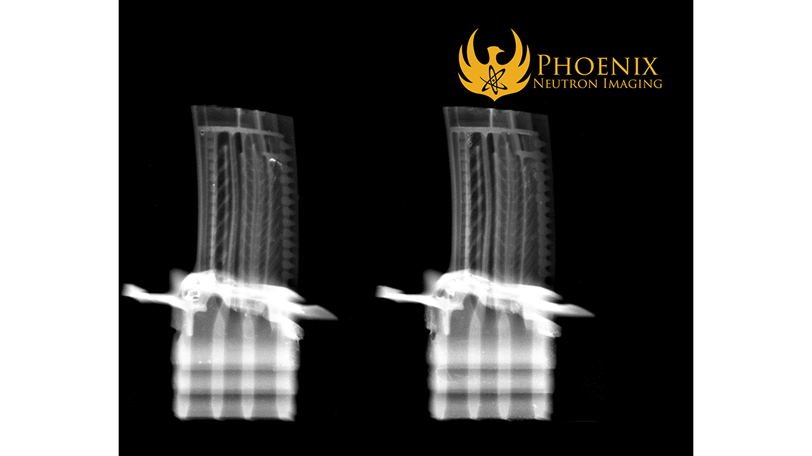
Residual ceramic core within a turbine component can cause catastrophic damage to an engine. The ceramic core is what defines the internal dimensions of many turbine components and after metal alloy is cast to form the part, the ceramic core remains inside. The core is then removed through a chemical process, but complete removal needs to be confirmed. N-ray can provide this confirmation. To do this, the parts are thoroughly washed externally and internally with a solution that contains a material called gadolinium. Gadolinium is used because it can almost completely absorb neutrons. The gadolinium wash completely covers and impregnates any residual ceramic core that may be present. The parts are then dried and positioned in front of neutron beam and either a film or digital detector then captures the neutron radiograph or digital image. Any residual core material can then be easily identified on the N-ray Image. If any ceramic core material is found on an N-ray, that serial number can be reprocessed. Figure 1 shows ceramic core material within the internal cavities of a turbine part.
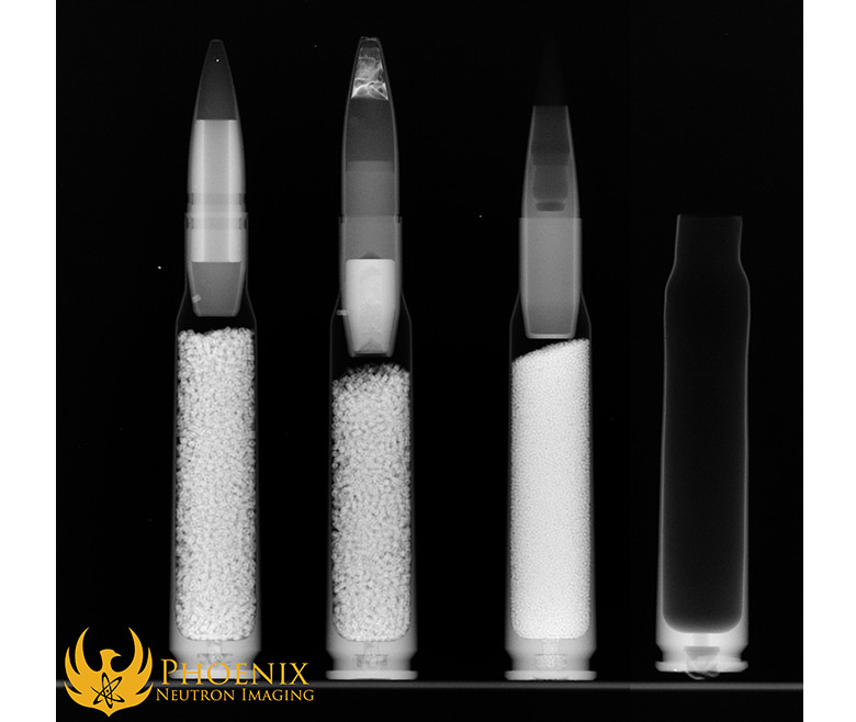
Another unique flaw that relies on N-ray for detection is proper distribution and density of internal explosive materials in artillery/ammunition shells. For this inspection, the ammunition is presented simply by being placed into the neutron beam and imaged. The neutrons interact with the various elements within the component and they can then be interpreted and identified on the N-ray image.
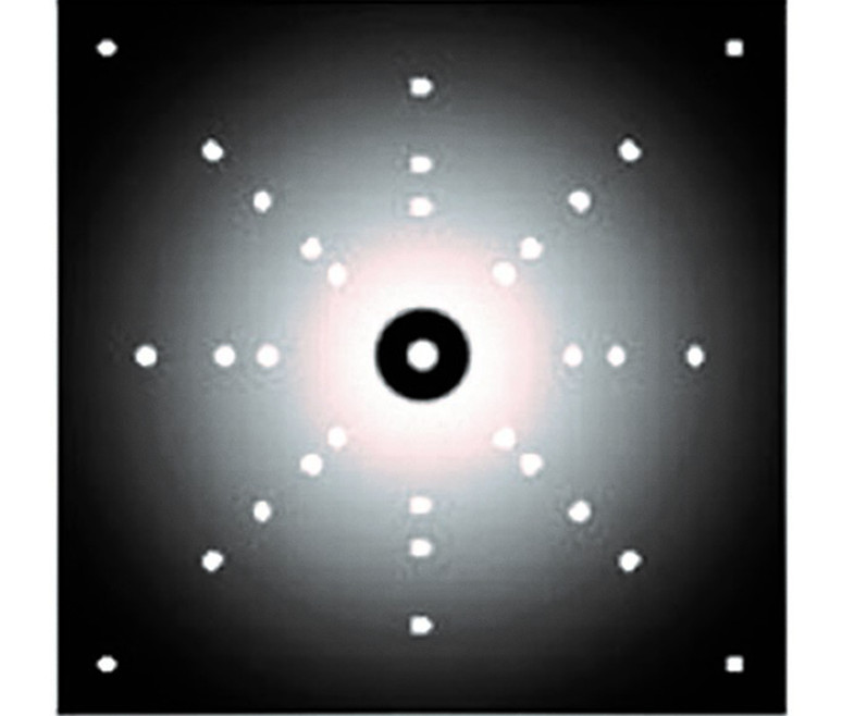
X-ray diffraction (XRD) is another method that is used for specific flaws. One of these flaws is unwanted primary and secondary angle orientation in single crystal turbine components. This flaw is again one that if not detected could lead to failure. The orientation of the crystal lattice structure is designed to provide the maximum durability of the component. If the orientation is not optimal, this can lead to reduced mechanical properties and a weak link.
XRD is a specialized technique within the digital X-ray method. With XRD for primary crystal orientation, the X-ray beam is focused on the sample at an incident angle instead of at a specific larger area of interest. This focus on the sample is assisted by tooling that places the sample in the known and desired primary orientation. The X-rays are activated and upon contacting the sample, they slightly penetrate and they interact with the material’s atom structure. The sample does absorb some portion of the X-rays, but another portion of the X-rays will diffract or scatter from the sample at the same incident angle at which they were focused. These diffracted X-rays will provide a pattern of the atom lattice structure which is then compared to the desired pattern. If the pattern is within the acceptable tolerances, then it is passed and allowed to continue processing, if it is not acceptable, the sample is discarded. Figure 2 shows an image of a single crystal lattice structure.
XRD is also used extensively for stress measurement. In this application, the method is again measuring the crystal lattice, but instead of inspecting for the atomic orientation, it is focused on strain at the atomic level. The X-rays are still focused in specific areas, and the sample absorbs some portion of them, but it is the diffracted X-rays that are used for evaluation. For stress measurements the diffracted X-ray data are used to measure the amount of spacing change between the atoms. This spacing, just like the orientation patterns, have known and desired values and the actual measurements can be used to assess if the stress levels are acceptable or not.
N-ray and XRD are just two examples of NDT methods that are used to find flaws that are not openly discussed or well known. There are many of these, not as common inspections, for various industries and some that are very particular to the materials/component(s) manufactured.
Always remember that flaws can come in many different shapes, orientations, and sizes and that they can be minor material differences, surface imperfections, or anything that is not supposed to be on or in a component.
Looking for a reprint of this article?
From high-res PDFs to custom plaques, order your copy today!


