Measurement Matters
If you can’t measure it, you can’t sell it.
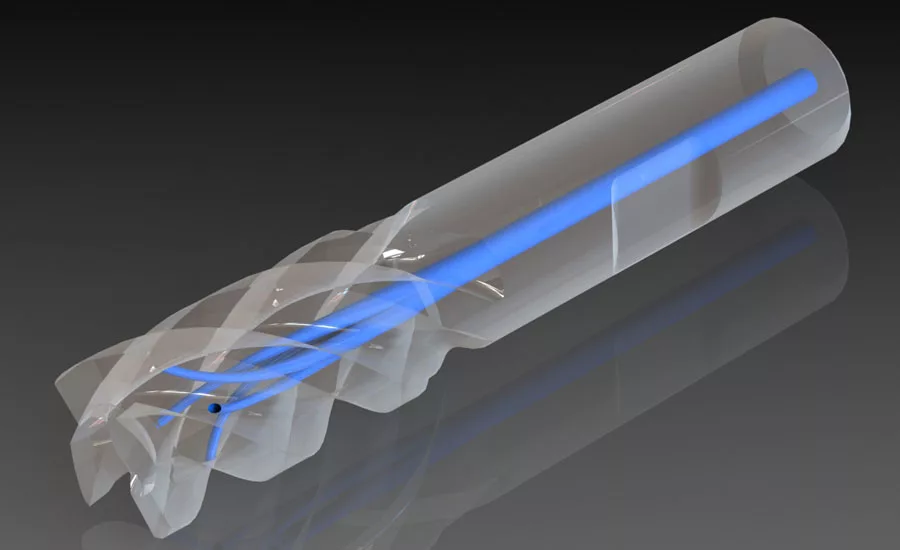
A hard-to-measure part is shown here. Source: Neomek Inc.
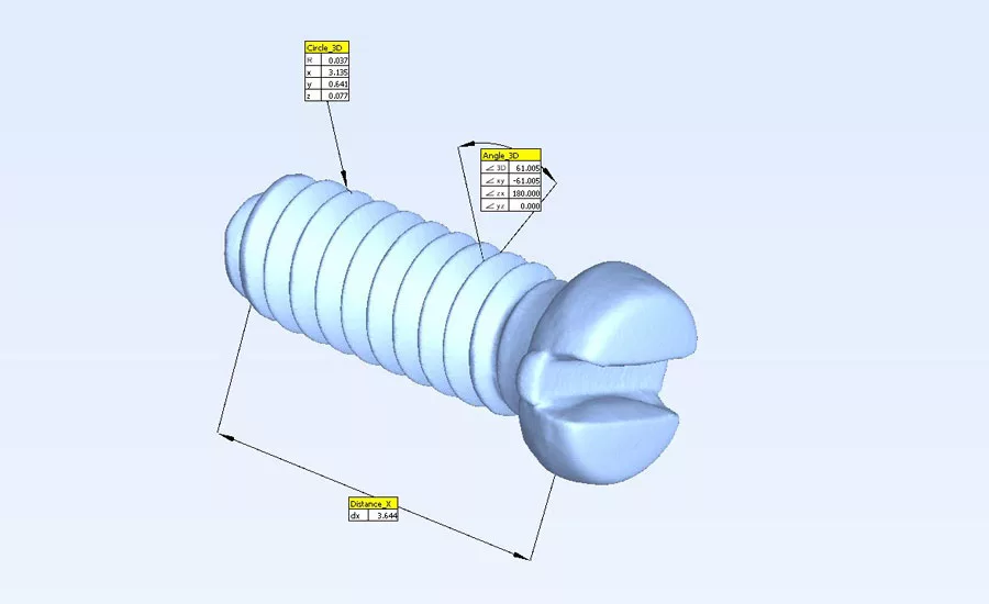
This is an STL of an eyeglass screw scanned at 5 µm.
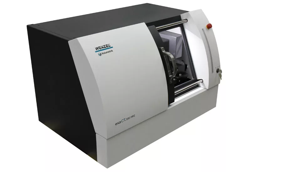
This machine is capable of scanning at 5 µm.
Visit a manufacturing industry trade show and you will see brightly colored parts on display on the 3D printing vendors’ stands. The vendors compete to create the most intricate parts, the more complex the better, and best of all if the parts couldn’t have been made before additive manufacturing existed.
I was recently at a trade show and was looking at a tiny metal part which could not have been made by any other means than additive manufacturing. The vendor’s representative pointed out to me the tiny holes he tells me go “all the way through.” I ask him what I thought was a reasonable question: “How do you know they go all the way through?” His reply: “Because the holes were in the CAD”— not a good answer for someone asking the question from an inspection perspective!
It is widely accepted that if 3D printed parts are going to compete with other technologies they must be able to compete on price, material properties and material integrity, but what is often overlooked is that the parts will need to meet the same dimensional integrity standards considered normal by manufacturers using other methods.
It is a misconception commonly held by the users of 3D printers and encouraged by the vendors that the parts made by 3D printers are made perfectly and within the stated accuracy of the machine and so don’t need to be checked. This is, from the perspective of a quality controller, completely ludicrous but it is a widely held view.
As 3D printing processes progress to being able to print higher quality materials at greater speed, larger (and smaller) part sizes and greater accuracy, the industry is looking for wider markets for their end products outside of research and development, tooling and short-run prototypes to compete head-on with molding and subtractive technologies for larger volume production parts.
While everyone in 3D printing is understandably excited about pushing the boundaries of what can be made, and eager to reach the goal of getting orders for production parts, they are forgetting some basic facts. There are rules to the game of selling production parts that are acceptable for safety critical industries like medical, aerospace, defense and automotive and rule number one is that you have to be able to validate that the parts that you make are what you say they are. Further to that rule are more rules that say what is an acceptable way to go about this validation task. These rules were built up over 150 years and they aren’t going to be abandoned because they are inconvenient to the 3D printing industry. In one sentence: If you can’t measure it, you can’t sell it.
Traditional machine tools are sturdily constructed and have a century’s worth of knowledge invested in the technology that controls their output. Even so, the parts they produce are expected or indeed required to be measured by an independent checking gage even more accurate than the machine that made the part. Dimensional measurement machines used for that purpose such as CMMs are sturdily constructed, often from granite, with precision air bearings, sub-micron scales, electronically error-mapped and kept in a temperature controlled environment. This is because experience over decades has taught us that if we are really interested in being able to maintain accuracy of measurement then this is what is required. Given that not all 3D printers are sturdily built or equipped with the precision mechanisms and controls expected on a conventional machine tool it is unconscionable that they should get a free pass and be exempt from the gage requirements that apply to every other process making production parts.
We are increasingly being asked for solutions to measuring parts and assemblies that did not exist in the past that are being held to the same standards of dimensional integrity as industry standards require. In addition to 3D printed parts, parts made by methods such as investment casting, plastic and metal injection molding as well as electrical and chemical erosion techniques can also be so complex as to be beyond the capability of conventional measurement.
Other factors that contribute to the difficulty of measurement include highly polished surfaces that cannot be touched, precision machined surfaces that have such tight tolerances on them that only a tactile solution will suffice, or maybe a combination of these that might also make a part impossible to inspect.
Options for inspection
We are in a privileged position here in that we have a wide range of measurement solutions available when presented with a difficult to measure part. Sometimes a single technology will meet all the requirements of the measurement task; a high speed optical CMM for example has the speed, accuracy and ability to measure polished surfaces without touching them that meets the needs of many complex medical or aerospace parts. Where optical CMMs, laser and blue light scanning options fall down is when the part or assembly has internal features that need to be measured that cannot even be seen from the outside. If the parts have been designed with inspection in mind it might be possible to access internal geometry with a conventional CMM, but if not, computed tomography (CT scanning) is the only option available.
CT Scanners to measure 3D printed parts
Most people are familiar with the term CT scanning from its medical application also known as “CAT scans.” In this application its use is nondestructive testing on living people and indeed its first industrial application was for nondestructive testing of parts, as a 3D X-ray looking for cracks and porosity in parts. The fact that CT allows the creation of a 3D image that can be measured and compared to a CAD model make it an ideal technology for inspecting parts with hidden features that could not be accessed by conventional measurement equipment.
Measuring with a CT scanner involves the creation of a “virtual part.” Either as an .stl file, or as an image in 3D “volume data” that is sufficiently accurate to be measured by metrology software.
There are different approaches to how that measurement takes place. Where there is a CAD model of the nominal part the most likely method to use for production parts would be to use the same software that might be used on a CMM to measure the “virtual” rather than a “physical” part; It’s a similar process only much faster. Another approach is to line the scan up against the CAD and create a color map of the part which is instructive but not as good as the virtual CMM approach for generating SPC data.
In the same way that a conventional measuring machine such as a CMM dedicated to measuring production parts is going to be sturdily built, likely to be on a granite base and contain the highest precision parts available, similarly, a CT machine for metrology will be built the same way and probably by a manufacturer of other metrology machines.
CT Scanners for Metrology
The cost of a CT machine for measuring parts is likely going to a similar price to a high-end metal printer making similar sized parts. Whereas companies making production parts on machining centers have come to accept (often grudgingly) that they need to invest in quality systems and inspection tools, few in the 3D printing community currently see this as a necessary part of the investment they need to make in order to be able to produce production parts. This will change as their prospective customers in the aerospace, medical and automotive industries make the case that if you can’t measure it, you can’t sell it.
Looking for a reprint of this article?
From high-res PDFs to custom plaques, order your copy today!


