NDT Applications: Flow-Testing Sharpens PCV Design
For such small, seemingly simple devices, with only one moving poppet and a spring inside, automotive positive crankcase ventilation (PCV) valves must meet surprisingly rigorous performance specifications. Each new valve must prove that it will admit specific amounts of airflow at a number of different vacuum levels. To satisfy such specifications, Novo Products Inc. (Holland, MI), found that experimental testing becomes an intergral part of the design process.
"We've never been able to develop any design formula for this," says Novo manufacturing engineer Brent Veeneman, a certified manufacturing engineer. "It's largely a trial and error process."
When customers began requesting prototype flow-test data presented in graphical form, Novo had to find design-test capabilities that no known instrument could provide. They solved the problem, and cut design testing time, with a customized mass-flow leak-tester and PC-based test-networking software.
The PCV valves must properly relieve engine crankcase pressure to prevent backfiring or blown gaskets and seals. To do this, the valves regulate pressure outflow from the engine by means of a tapered poppet moving in and out of a tapered orifice. The orifice outlet is connected by tubing to the engine's air/fuel intake. When air/fuel intake vacuum is low, spring tension holds the poppet open so engine gases can circulate back to the intake for reburning. Increasing vacuum gradually pulls the poppet closed.
The PCV valves have to have a balance among the internal geometry of its poppet and orifice, the force of the spring and the level of vacuum.
Customer specifications define the valve's size, shape and flow values desired at designated vacuum levels, termed "Delta Points." Vacuum levels typically range from 1 to 20 inches of mercury (InHg), while flow values might be anywhere between 0.2 and 8 cubic feet per minute (cfm). Each valve design must be verified by flow-test data gathered at up to 20 Delta Points.
Testing is complicated by the time needed to let airflow stabilize at each Delta Point before the flow is measured. Other complicating factors are the airflow's absolute pressure (psia) and temperature, which cause vacuum pressure and air density to vary.
Novo first tried to combine a commercial flowmeter with a home-made valving system. "It worked," Veeneman recalls, "but manual data gathering was time consuming and we weren't confident about its accuracy." Seeking something more reliable, they called upon InterTech Development Co. (IDC, Skokie, IL), a firm that had provided Novo with several turnkey assembly systems with integrated leak-testing functions.
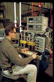
Collaborating with IDC, Novo first built a two-station production tester with a pair of IDC M-1035 mass-flow instruments. One tool was used for valves operating in the 0.2 to 2 cfm flow range, the other for valves operating in the 2 to 6 cfm range. Both had programmable vacuum regulators covering the full 1-20 InHg range.
In a typical test, a M-1035 sequences each valve through three test programs, one for each Delta Point. During each Point's test, the instrument displays vacuum pressure and flow rate, comparing both against pre-set limits and signaling either accept or reject.
With the M-1035's ability to program precise vacuum points and flow limits, and recall test data from its last 1,000 tests, the tester became the instrument-of-choice for design testing. "When new valve designs began calling for full 20-point curves spanning both low and high flow ranges, we would test the low-flow and high-flow delta points on whichever M-1035 had the appropriate range, then collect the data from both and manually plot the curve by patching the segments together. That puts a void in the curve where the data jump from one instrument to the other," Veeneman admits, "and it risks possible calibration discrepancies between instruments, but it was better than anything else we had."
Six months after production start-up, Novo's high-flow valve production ended temporarily, so the high-flow production instrument was refitted with a low-flow transducer to provide more testing capacity for the increasing volume of valves in that range. "After that," he says, "the only way we could do full-curve prototype testing was to fill in the missing-range points with our old home-made tester, which made the task even more difficult and less reliable. We needed a full-range tester and a better way to graph the data, but nothing like that existed."
Building upon the vacuum-regulated M-1035 platform, InterTech proposed a customized version of that instrument. Its mass-flow transducer would be replaced with an external laminar flow element having a master lab calibration accuracy of ±0.6%-of-reading across the desired flow range of 0.2 to 8 CFM. This would be coupled with a differential-pressure transducer certified at 0.15%-of-reading, an absolute-pressure transducer certified for 0.3%-of-reading, and an airflow temperature sensor.
While the M-1035s in production testing provide mass-flow transducer accuracy of ±0.5%-of-range, which satisfies Novo's short CFM requirements, percent-of-reading capabilities are essential in their lab counterpart to assure accuracy at all points along its extended CFM range. Adding the high-accuracy transducers and temperature sensor, along with custom programming, enables the lab's M-1035 to measure flow values at ambient temperature and pressure, but display and record them as corrected to buyer-specified standard conditions.
For increased test program and data storage, a PC running a customized version of InterTech's S-3085 Monitor Software was added. The customized software lets the PC store test parameters for up to 20 Delta Points for each PCV valve design, including calculations for correcting atmospheric pressure and temperature to buyer specifications. It also allows the PC to display real-time results for all Delta-Point tests combined into a single continuous graph, depicting changes in both vacuum level and airflow over time against each Point's upper and lower limits. Using a PC allows full-range curves to be seen on a single screen, exported to MS EXCEL format, printed out or e-mailed.
Adding the PC served other essential purposes as well. While a standard M-1035 can store and recall enough test programs for up to 33 three-point production tests, the lab tester needed greater storage capacity. As each Delta-Point test requires a separate test program, 20-point tests for each of 7 PCV valve models tallies 140 programs. That total is certain to grow as more valve models come into Novo's product mix.
The S-3085 software enables the lab tester's PC to store 2 million test records per 100 MB of available space. It also allows the PC to recall stored test data either in total or using selection filters such as date, accept/reject results, or causes of rejects. Test data for multiple samples of the same prototype can be merged to show both the data table and full-range curves comparing average flow performance vs. high/low extremes across the sample population.
The IDC system has speeded prototype testing by 40 to 50 percent, design time by about 20 percent and the data presentation makes the data easier to interpret. "Real-time graphic display lets us see and document in greater detail exactly how a design is behaving at all times during its cycle," he says. "We no longer have to plot curves manually or patch curves together."
InterTech Development Co.
(847) 679-3377
Reply 622
Looking for a reprint of this article?
From high-res PDFs to custom plaques, order your copy today!


