Computer Inspection Aids Six Sigma Efforts

Six Sigma is a highly disciplined process that focuses on developing and delivering near-perfect products and services. This not-so-easily achievable goal is defined by its developer, Motorola, as a “business improvement process that focuses an organization on customer requirements, process alignment, analytical rigor and timely execution.“
At the heart of Six Sigma is DMAIC (define, measure, analyze, improve and control), a systematic process that eliminates unproductive steps, helping companies fulfill the vision of Six Sigma.
New computer-aided inspection (CAI) technologies can improve the “measure“ and “analyze“ part of the DMAIC process, making them valuable tools in the Six Sigma approach to quality. CAI also fulfills the goals of process alignment, analytical rigor and timely execution.
The CAI alternative
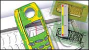
CAI advantages include re-peatability, speed, portability and direct correlation to 3-D computer-aided design (CAD). Noncontact scanners used in CAI collect millions of points in seconds, and these scanners are combined with new software that processes the data quickly and automatically to provide instant graphical comparisons between CAD models and as-built parts. CAI can capture and process free-form surfaces and sheet metal, and there is no physical size limitation for the part being scanned. CAI software can handle both the dense data from noncontact scanners and critical points from coordinate measuring machines (CMM).Two noncontact measurement systems are widely used for CAI: 3-D scanners and laser trackers. The scanners are commonly used for range finding and they work by projecting a laser beam onto an object and measuring its reflected image with a positioning sensor. The scanners are fast and can be mounted onto an existing CMM.
Laser tracking is also known as interferometry. A laser tracker calculates the relative distance between points along a single axis. By knowing the wavelength of the emitted light and the distance between edges of the part, the distance between two points can be computed.
Data collected from noncontact measurement systems is compared automatically in CAI software with the corresponding CAD model, which is considered the design authority. Because noncontact scanners collect millions of points in seconds, the system starts with a significant amount of information about the part and this global approach to collecting data lends itself to automation.
Typically, the points and CAD models are aligned by datum or feature. These datums and features exist on the CAD model, but not in point data. The CAI system automatically creates datums and features on the points, eliminating time-consuming user interaction.
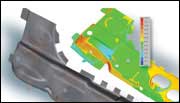
After aligning the scan data with the CAD model, the CAI software compares the two and creates a common result model that can be used for 3-D and 2-D analysis. The 3-D analysis relates the results directly to the CAD model, which is much more intuitive than comparing 2-D drawings with 3-D models. Instant go/no-go visualization is provided, as well as detailed geometric dimensioning and tolerance (GD&T) analysis. Measurements can be done using a 3-D model or a 2-D cross section.
The CAI process is applicable to a wide range of quality-assurance tasks, including first-article inspection, tool validation, wear analysis, sheet-metal inspection, 2-D and 3-D GD&T analysis and reporting. CAI software can work with data from noncontact scanners or CMMs.
Beyond analysis, CAI provides automated reporting in standard formats such as HTML, PDF, Microsoft Word and Excel. A CAI report contains rich visual images, model annotation, and tabular numbers that improve communication among key members of a Six Sigma team. Easy-to-understand reporting in standardized formats is especially significant in today's distributed work environments, where design, engineering and manufacturing are likely to take place in different parts of the world.

Handling the data load
The massive amounts of data generated by noncontact scanners creates a challenge for traditional metrology software. Until recently, large data loads could bring even the most powerful inspection systems to its knees. Fortunately, new CAI software based on complex mathematics and geometric algorithms is up to the processing task. In tight integration with the scanner, the software creates a complete CAI solution, making it possible to meet these frequently stated customer demands:
• accuracy of 0.001 millimeter to 0.005 millimeter
• speed of more than 10,000 points per second
• portability for in-process measurement
• an open system for rapid conversion to standard or native CAD formats
• automatic align, compare, evaluate and report process
• repeatable setup, process and results
• ease of use so it can be deployed on the shop floor by inspectors with no CAD training
• go/no-go displays that enable an automatic pass/fail check with pre-defined tolerances

Digital product development
CAI software will become a mainstream application and an essential part of the digital product development cycle. Pushing quality inspection into earlier phases of the development cycle will speed product development and ensure greater quality. As supplier networks continue to expand and products are increasingly differentiated according to quality, how well a company implements the inspection process can be a make or break factor in the marketplace.CAI can be a component of this process. The technologies complement, rather than replace, the CAD/CAM/
CAE systems manufacturers already have in place and can generate almost immediate benefits. It has allowed electronics manufacturer Square D, for example, to align its 3-D design processes with quality inspection. The result has been better quality control and a reduction in inspection time for a typical part from three weeks to a couple of days. In another example, a leading European auto manufacturer has used CAI to automatically align and compare scan data of an as-built part with the original CAD data to determine exactly where variations in the geometry occur and to analyze how deviations might impact the part's functionality.
Early CAI adopters such as these are accelerating their inspection processes and increasing the value of their existing CAD/CAM/CAE tools, giving them the potential of getting ahead of their competitors in fulfilling the promise of Six Sigma.
Supporting Six Sigma
CAI enables manufacturers to find problems early in a product's lifecycle, saving time and money. It helps achieve measurable improvements in three of the four major Six Sigma areas defined by Motorola: process alignment, analytical rigor and timely execution.It makes process alignment possible by providing a common inspection model that can be used across different product development steps, including CAD, CAE, mold design, first-article inspection, surface contours and GD&T.
It fulfills the need for analytical rigor by enabling analysis of more and better-defined information than possible using traditional metrology processes.
Finally, it improves timely execution, not only through faster processes, but by enabling better alignment with existing 3-D technologies and opening up the possibility of greater collaboration among design and manufacturing groups.
TECH TIPS
• Six Sigma uses a systematic process called DMAIC (define, measure, analyze, improve and control to eliminate unproductive steps and reduce defects.• Computer-aided inspection technologies can improve the measurement and analyze aspects of DMAIC.
• Using 3-D scanners and laser trackers, millions of points of data can be captured and software can immediately process this data to compare it against CAD models.
Looking for a reprint of this article?
From high-res PDFs to custom plaques, order your copy today!


