Quality test & inspection: Mark Quality Equals Part Quality
With so many manufacturers today implementing direct part mark (DPM) identification programs for part traceability, the need to control the part marking process is becoming increasingly important. The original quality of a 2-D code, which serves as a part's permanent identity, can greatly affect the readability of a part as it travels through the manufacturing process, through the supply chain and ultimately through to the end use of the part.
Because the quality of a direct marked 2-D code is critical to the success of lifetime part traceability, many manufacturers view the 2-D mark as a critical attribute of the part itself. Loss of a part's identity because of poor mark quality means that the part cannot be processed in the manufacturing plant or be used in the supply chain. For this reason, parts suppliers and manufacturers are beginning to require a 2-D mark verification capability in order to confirm that part marks meet the quality levels set forth by industry standards.
From a process control standpoint, controlling the quality of the mark that gets applied to the part is a critical element to successful part tracking applications. By understanding the root cause of poorly formed codes using universal standards, manufacturers can trouble shoot marking equipment, better maintain the equipment, and prevent bad codes from entering the manufacturing and supply chains.
From a contract compliance standpoint, a growing number of companies today need DPM verification systems to ensure that they are marking codes that comply with specific contract requirements. For example, to meet the objectives of the U.S. Department of Defense (DoD) Unique Identification (UID) Program initiative, suppliers are now required by contract to mark and verify DPM codes on items having an acquisition cost of more than $5,000, serialized items, mission-critical items, and spared or repaired items that meet Item Unique Identification (IUID) requirements. By complying with this regulation, suppliers improve their own ability to read codes, while helping the DoD improve data capture, part lifecycle management activities and logistics support.
Contract compliance also is starting to come into play in other industries. Automotive companies, for example, want to be confident about the readability of parts before the parts arrive at the assembly plant. Thus, many of these companies are beginning to push the burden of DPM verification down the supply chain.

DPM verification defined
In its most basic form, DPM verification is the process of visually inspecting the quality of a direct marked 2-D code. A DPM verification system, which may be deployed directly on the marker or as an independent station, is made up of integrated lighting, optics, camera, part fixturing and verification software. DPM verification systems operate by capturing and analyzing the image of a code and rating the image on a number of quality assessment metrics.These quality metrics are based on industry specifications, as well as supplemental quality metrics a vendor may have designed into the DPM verification system to optimize process control. The DPM verification system then generates an overall score or grade for the code and provides process feedback about the marking equipment that manufacturers can use for preventive maintenance. For process control, DPM verification systems monitor variations in the quality of a just-applied code to quickly detect problems at the marking station.
When considering a DPM verification system, it is important to understand the difference between DPM code reading and verification. While both are necessary for successful parts tracking, reading and verification systems are designed to accomplish different tasks and have their own set of unique challenges.
The goal of DPM code reading is to read a code as quickly as possible despite the appearance of a code and report the results. With DPM verification systems, the goal is to confirm that the mark meets an acceptable level of quality as defined by particular quality specifications and industry standards.
In order for a verifier to analyze the attributes of a mark that affect readability, it needs to be able to form a consistent image of the mark. To form such an image, a DPM verification system must operate under tightly controlled conditions. Lighting, part fixturing, camera resolution and optical settings all need to be configured based on the specific surface characteristics of a part and the marking method used and redefined for each new verification application.
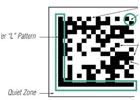
Data Matrix 2-D symbology has emerged as the standard code type for parts tracking. These Data Matrix codes are marked on the part using several methods. Common methods include dot peening, laser engraving, electro-chem etch and ink jet marking. The marking method used is typically defined by engineering and takes into consideration acceptable marking methods for a particular part or material, the life expectancy of the part, material composition, environmental wear and tear, surface texture, the amount of space allotted for a code and the amount of data to be encoded on each part.
Implementation guidelines
Correct setup of lighting, optics and other components is necessary to achieve effective image formation and is critical to the success of any DPM verification application. Following are some general image formation guidelines to follow when setting up a DPM verifier:- Camera resolution. In verification applications, a good rule of thumb is to have a minimum cell resolution that is two to three times higher than that required for reading DPM codes. In order to achieve consistent, repeatable results, this means a verification system should be equipped with an optical magnification that provides a minimum resolution of 100 square pixels per module.
-
Lighting. Because they need to handle a wide range of marking methods and part surface characteristics, DPM verification systems need to have the ability to accommodate a variety of lighting approaches, including:
- Bright-field illumination. Diffused light is directed at the marked code 90 degrees ±5 degrees. This method is ideal for high-contrast printed or marked codes on nonreflective surfaces.
- Dark-field illumination. Light is projected at a low angle to the part surface causing any variations to deflect light up into the camera. This technique is ideal for dot peen and highly reflective laser etched codes.
- Diffuse dome illumination. This provides a nondirectional, soft illumination free of harsh shadows that is well suited for highly specular objects. This technique is ideal for imaging marks on curved highly reflective surfaces and dot peen codes on rough surfaces.
- Ambient lighting. The result of a verifier should not be influenced by changes in ambient lighting conditions. This means the verifier should either be shrouded to eliminate the effects of ambient light or should apply a cut filter that only allows light from the verifier's light source into the camera.
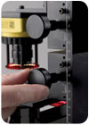
- Part fixturing. How a part is presented to the verification system has a significant impact on a DPM verification system's ability to generate consistent and meaningful results. As a general rule of thumb, parts should be consistently positioned in the center of the camera's field of view and at a consistent working distance.
- Set-up routine. To establish a baseline during system setup for lighting, optics and resolution, it is recommended that a set-up routine be performed. This is essential for achieving a repeatable and reproducible setup of the DPM verification system.
Types of DPM verification systems
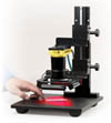
Operators today want to perform DPM verification using in-line fixed mount, benchtop and handheld verification systems.In-line fixed-mount DPM verification systems can be mounted on the marking machine, directly after the marking station or above the fixtured part at the marking station. Fixed-mount systems incorporate precisely mounted components and are designed so that the entire image formation system is configured to the specific marking method and surface characteristics of the parts being marked. These systems typically provide extremely consistent and repeatable performance.
Stand-alone or benchtop-fixed mount verification systems are used as first article inspection tools or as incoming quality inspection stations. Stand-alone verifiers incorporate stand, verifier and lighting to accommodate flat parts, nameplates and other small parts that can be brought to the station.
The demand for handheld devices that can provide both verification and reading capabilities is being driven by applications where parts are too large to be placed onto a fixed mount station. While handheld solutions promise a high level of ease-of-use and convenience, there are currently no handheld verification systems on the market that take into account the considerations of implementing repeatable DPM verification. Solutions are now under development to address this need.
Tech tips
- DPM verification is the process of visually inspecting the quality of a direct marked 2-D code.
- A DPM verification system is made up of integrated lighting, optics, camera, part fixturing and verification software.
- DPM verification can help manufacturers improve the marking process, increase read rates, lower the cost of rejected parts because of unreadable codes and ensure that parts do not lose their lifetime identity.
- Data Matrix 2-D symbology has emerged as the standard code type for parts tracking.
Looking for a reprint of this article?
From high-res PDFs to custom plaques, order your copy today!


