Case Studies: NASA and Flowserve Collaboration Launches New Valve Technology

At the John C. Stennis Space Center near Bay Saint Louis, MS, NASA engineers had a problem. Their process of testing various rocket propulsion systems was running into an expensive snag, hanging on high-pressure control valves that needed to be switched out and replaced for each test.
The center uses these valves, in both ambient and cryogenic configurations, for the flow control of oxygen, hydrogen and other propulsion propellants used in their rocket engine and component test facilities. Stennis, the main propulsion testing center for NASA, is where the space shuttle main engines are tested and certified.
Propulsion tests can include measurements of temperature, pressure, flow regulation, engine design validation, and material and component performance. Engineers at Stennis have historically employed in-line, top-entry valves in these high-pressure performance tests because the top-entry design was perceived to limit external leakage.
But in-line, top-entry valves have their drawbacks. They are expensive and have long face-to-face lengths of up to six feet. NASA also needed the flexibility to change the trim size on its valves to meet the differing flow control requirements of individual tests. Because the trim size cannot be changed on the type of in-line forged valves that NASA normally uses for these applications, the engineers were forced to stock multiple valves for a single test sequence-for example, testing an engine or component using several propellant flow rates.
To find a solution, NASA engineers turned to Flowserve Valtek Control Products (Irving, TX). NASA initiated contact to see if the company could address its needs. The contact between NASA and Flowserve was originated through the Stennis Propulsion Test Directorate, which directs and manages the operational and engineering functions for rocket engine testing at Stennis.
Considering the drawbacks of in-line, top-entry valves, NASA engineers thought a solution might be to try an in-line, split-body valve, which would allow them to change trim sizes without taking the valve out of service to meet testing requirements. A split-body valve would provide tremendous flexibility in testing and save on valve inventory expense.
NASA engineers were cautiously optimistic. In their experience, split-body valves, particularly those used in cryogenic applications, were prone to external leakage and seat leakage. Additionally, in NASA's high-pressure engine testing applications, engineers who wanted to use a split-body design were typically design-limited to an offset body as opposed to an in-line design. This is because in-line split-body valves typically have to use castings instead of forged body assemblies. NASA prefers in-line valves because they are inherently easier to work with, as their body geometry enables simpler installation than that of offset valves.
Field and design engineers from NASA and Flowserve worked to create a valve that would simplify installation and maintenance, allow for trim-size changes, and minimize inventory requirements, thus reducing cost. Combining NASA's experience with high-pressure aerospace applications and Flowserve's application, design and testing experience in the liquid natural gas, upstream oil and gas and aerospace markets, the team generated a set of technical solutions that met NASA's requirements for high-pressure, cryogenic, rocket propulsion tests.
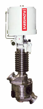
Because NASA's requirements included both ambient and cryogenic applications, Flowserve began by integrating its control valve technology into the valve's seals, stem packing and mechanical design for the required temperature ranges. In the first stage of the process, the body of the valve was divided into an upper and a lower section, with its seat ring in between. To maintain the stem packing at an acceptable sealing temperature for cryogenic service, the design team added heat-absorbing fins to the upper-body section of the valve.
The valve body was made of stainless steel and project team engineers designed the seat ring in a nickel-based alloy with a coefficient of thermal expansion less than that of the body material. This enabled the body surrounding the seat ring to contract more than the seat ring when the valve interior was cryogenically cooled, preventing external leakage at the body-seat joint. Engineers also machined the seat ring to have small, raised-face sealing surfaces on both sides of the seal groove, which concentrate the body bolt load over a small area and work to prevent external leakage.
Preparing For Launch
The new valve's body bolt circle design is different from those in conventional high-pressure control valves, with half of the bolts clamping the split-body together from the top, and half from the bottom. This design allows a short, clean flow path, minimizing frictional flow losses and shortening the face-to-face length of the valve. While a conventional class 4500 valve with a nominal heat capacity at constant volume, or Cv, of 120 has a face-to-face dimension greater than 40 inches, the NASA-Flowserve split-body valve is only 25.5 inches long.
"This was an entirely collaborative and iterative process, with contributors from NASA and Flowserve providing their expertise and contributions to the success of this project," says Michael Yentzen, an engineer on the project who is now a legislative affairs specialist at NASA headquarters in Washington, DC.
"You could truly call this a team effort," says Karlin Wilkes, Flowserve Valtek control valve marketing manager. "We spent a year working together, and the end result has really paid off."
Mission Accomplished
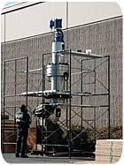
Pre-launch tests included cryogenic testing at Flowserve labs, then at Stennis, and then together in final validation tests. At Stennis, the valve was bubble-tight at 11,250 psig, even at cryogenic temperatures. Following the design process, NASA ordered additional Flowserve split-body valves in varying sizes for other applications in the same system.
Applications for the additional split-body valves include transfer-line isolation and tank venting. NASA has slated the split-body design as a flow control valve in an RP-1 (refined petroleum) fuel run-line in a facility currently under construction at Stennis.
"We're very pleased with the product we developed," adds Yentzen. "This valve design will save NASA a significant amount of money and will make rocket test operations at Stennis simpler and more efficient."
Benefits
-Field and design engineers from NASA and Flowserve created a valve that provides flexibility in testing and saves on valve inventory expense.
-The valve design is expected to make rocket test operations at Stennis simple and more efficient.
-The design of the valve allows a short, clean flow path, minimizing frictional flow losses and shortening the face-to-face length of the valve.
(801) 489-2645
www.flowserve.com
Looking for a reprint of this article?
From high-res PDFs to custom plaques, order your copy today!


