Quality Innovations: Automate CMM Programming
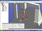
PAS CMM is an off-line solution that allows the generation of CMM programming suitable to any CMM machine in a DMIS environment. Source: PAS Technology
Inspection, as any quality professional knows, is not without its challenges. Though an essential part of the manufacturing process, it can be both expensive and labor intensive, and create bottlenecks in getting products out the door.
Coordinate measuring machine (CMM) programming in particular is often a bottleneck in the entire design and manufacturing process, says Sam Golan, president and chief executive officer of PAS Technology (Cresskill, NJ), and the demand for highly accurate and complex parts increases the need for a better CMM inspection process.
CMM departments today may be considered one of the most expensive in the supply chain, Golan says. In addition, growing global competition is forcing companies to cut costs and trim delivery times.
“Definitely the industry needs to change,” Golan says, “And we help to do it as much as we can.”
New software from PAS Technology provides an automated link between the CAD domain of the 3-D model and drawing and the inspection domain of DMIS code.
PAS Technology’s CMM solution is an automated CMM programming tool that can save time, reduce cost and expedite delivery time, Golan says. Going from a computer-aided design (CAD) or computer-aided manufacturing (CAM) model to complete CMM program takes minutes-rather than hours or days-and eliminates CMM department bottlenecks.
“I believe that we resolved the issue,” Golan says. “We act to eliminate the bottlenecks and issues in inspection.”
PAS CMM is an off-line solution that allows the generation of CMM programming suitable to any CMM machine in a DMIS environment. It can be used by a non-expert user, and presents a return on investment of six to eight weeks on average, Golan says.

PAS CMM is currently the only solution that can generate CMM programs for multiple machines and metrology environments. Source: PAS Technology
It is currently the only solution that can generate CMM programs for multiple machines and metrology environments, Golan says, adding that it can help the industry become more competitive and lean, and change the notion of outsourcing. Golan is not a fan of outsourcing outside of North America and wants companies to consider the real cost of outsourcing.
PAS CMM supports all CAD standards such as STEP, IGES, DXF, VDA and PARASOLID. It does not generate reports; it generates a DMI file that will “tell” the current software what to inspect, how to inspect with the relevant tolerances and what report to generate. It generates two files, a CAD file and a DMIS program file. After those files are imported and converted to the operator’s current metrology software, it will appear on the screen as native program created by the operator’s current software, allowing operators to edit, modify and alter any string as they usually do with their own programs, Golan says.
The software was developed in Israel about five years ago. It is used by large aerospace, optical, defense and medical companies in Israel and the United States, and was released in the United States in late 2008. It is available for a flat fee, and PAS Technology recommends and provides three-day onsite training so operators can learn how the product works with their machine and their parts.
PAS Technology offers a 14-day test drive period, which includes two-hour, one-on-one Web training, generating a CMM program by the test driver with expert support, running a simulation on a test driver’s CMM environment, and addressing the test driver’s specific needs and challenges.
Technology Contact
For more information, contact:Sam Golan
PAS Technology
113 Palisade Ave., Cresskill, NJ 07626
(201) 266-6488
[email protected]
www.pastechnology.com
Specifications
The inspection of a feature is performed as follows:Looking for a reprint of this article?
From high-res PDFs to custom plaques, order your copy today!


