Understanding Optical Inspection
Optical inspection is an important part of the quality process in manufacturing. It can range from quick, subjective inspection by a person to automated quantitative inspection by a machine. It can be performed off-line, where the part is removed from the manufacturing process and brought to the inspection station; on-line, where the part is inspected without removing it from the manufacturing process; or near-line, where the part is inspected near the manufacturing process so it can be returned to the manufacturing process as quickly as possible.
The human eye is an optical detector that processes images projected through its lens onto the retina. As an object is moved closer to the eye, it appears to increase in size because the image covers more of the light sensors on the retina. At a certain point, a maximum magnification is attained, and therefore, by moving the item closer to the eye, the image goes out of focus. That distance is typically about 10 inches (250 millimeters). At that point, typical image resolution is approximately 4 thousandths of an inch (100 micrometers). An example of this would be seeing the space between two hairs where it just becomes obvious there is a gap between them. Resolving detail finer than that requires additional magnification.
Working clearance is particularly important in industrial environments since the ability to place and remove parts under test quickly and easily is important to overall inspection efficiency. The longer the working distance, the less likely that a part will touch and possibly damage the optics. Here, an optical comparator shows the working clearance between the part and the front lens. Source: Optical Gaging Products Inc.
Beyond the Naked Eye
Optical inspection is an enhancement to simple visual inspection performed with the naked eye because it involves the use of lenses to improve or enhance the image of an object so an accurate evaluation can be made about some characteristic or attribute of the object. Most optical inspection is qualitative, meaning that the operator makes a subjective interpretation of a magnified image. Optical inspection can be quantitative if the image is formed on an imaging device that provides data about the image that can be collected and analyzed. In those cases, optical inspection is actually metrology because it provides quantifiable measurements from the image.Unaided inspection by the eye is usually called visual inspection. When a lens or lens system is introduced, visual inspection becomes optical inspection. There are many examples of optical inspection systems and techniques, but there are fundamentals that apply to all of them.
The most basic optical inspection system is the single lens magnifier. It is typically a large lens mounted on an arm that attaches to a workbench. The operator positions the lens so he can hold a part with both hands while looking through the lens. Typically, an illuminator surrounds the lens to improve image quality instead of relying on ambient light alone. Simple magnifiers can improve imaging by three to five times and are useful for identifying cosmetic flaws and missing or incorrectly mounted components, for example.
A complex optical inspection device is the optical microscope. It combines a multi-element objective lens and a magnifying eyepiece to magnify the image of a part up to 800 times or more. High magnification limits the size of the area that is magnified, requires that the part be close to the lens and tends to have a very short range where the part is in focus. These restrictions tend to limit the use of microscopes in industrial manufacturing.
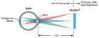
The human eye is an optical detector that processes images projected through its lens onto the retina. As an object is moved closer to the eye, it appears to increase in size because the image covers more of the light sensors on the retina. At a certain point, a maximum magnification is attained, and therefore, by moving the item closer to the eye, the image goes out of focus. That distance is typically about 10 inches. Source: Optical Gaging Products Inc.
From a manufacturing inspection point of view, there is a major difference between what the operator sees when using a microscope vs. an optical comparator. The eyepiece of the microscope shows a magnified field of view that the operator sees all at once. The screen of the optical comparator also shows the magnified field of view, but that image covers the 14-inch to 30-inch diameter screen.
Yes, the operator can step back and look at the entire FOV at once, but that is not how a comparator is typically used. The operator stands close to the viewing screen so he can zero in on a specific area within the FOV. This is particularly important when using the comparator to perform the measurement by comparison technique of optical inspection where the image of the part is directly compared to a master chart.
Yet another type of optical inspection device is the video measuring system. Its optical design is a variation on the optical comparator from which it evolved. Instead of the image expanding to fill the comparator viewing screen, the image strikes a camera detector. The operator views the magnified image output electronically from the camera on a monitor.
The camera in a video measuring system replaces the viewing screen of the optical comparator and eyepiece of a microscope. In essence, a video system provides high-magnification optical inspection with a very important difference-video measuring systems deal with more than a single FOV at a time.

All comparators magnify an image and project it against a glass or plastic screen, which is viewed by the operator. In this case, the viewing screen performs the same function as the eyepiece lens of a microscope. The magnification of the lens system and the diameter of the viewing screen determine the field of view and associated resolution. Source: Optical Gaging Products Inc.
Other Magnifications
All of these optical inspection devices magnify scenes just as a photographic camera does. The single lens magnifier has a fixed magnification that limits its usefulness for the range of possible applications such as resolving important details that require higher magnification. The versatility of an inspection system increases when it offers a range of magnifications. There are three common ways of doing this-lens replacement, a turret and a zoom lens.Optical comparators, microscopes and video measuring systems can be designed so that lenses can be removed and replaced. The operator typically uses a low-magnification lens to locate an area of interest on the part and then inspects the desired feature at a higher magnification. This design works, but is inefficient. There is too much handling of lenses with associated risks of damage and contamination. Also, it takes time to replace lenses, and replacement may be difficult if the part limits access to the lens mounting location.
A more efficient way of allowing magnification changes is to mount individual lenses in a turret. Both microscopes and optical comparators use turret-mounted optics that allow magnification changes without the need to handle each lens. The turret ensures that the optical axis of each lens is correctly aligned with each magnification change.
An efficient solution to the magnification change requirement is the zoom lens, which is commonly offered on video measuring systems. By using a zoom lens, the operator can view a scene at low magnification and zoom in on specific detail in that scene without changing the lens or rotating a turret.
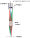
The optical design for a video measuring system is a variation on the optical comparator from which it evolved. Instead of the image expanding to fill the comparator viewing screen, the image strikes a camera detector. The operator views the magnified image output electronically from the camera on a monitor. Source: Optical Gaging Products Inc.
Common Ground
All of these inspection systems have similar considerations about optical performance that affect their usefulness and image quality. To be most useful, the optical systems in these devices should provide a large working clearance, be free from distortion and produce sharp, high contrast images.With simple lenses, working clearance or working distance, decreases as the magnification is increased. In other words, at higher magnifications the part needs to be closer to the lens.
In some optical comparators, a relay lens system produces an intermediate image that is in turn magnified by the projection lenses so the working clearance remains constant at the part. Changing the projection lenses changes the magnification without changing the working distance to the part, which improves productivity.
Another characteristic of traditional optics is that the size of the image changes on either side of focus. This can be a problem when measuring features in an image, as the apparent size may not equal the actual size. Telecentric optics avoid variations in image size as a function of focus position.
Working clearance is particularly important in industrial environments since the ability to place and remove parts under test quickly and easily is important to overall inspection efficiency. The longer the working distance, the less likely that a part will touch and possibly damage the optics. Also, the optical system must be clean for best quality imaging.
There is another metrology consideration to working distances when measuring parts that are not flat. The relationship between magnification and working distance means that it may not be possible to focus on a surface inside a part such as a bearing seat inside a metal casting. A short working distance means the lens or another part of the measuring system might strike the part before the area of interest is brought into focus.
All the discussion this far has been about imaging a single FOV. As mentioned earlier, video measuring systems perform high-resolution measurements over relatively large distances by using information from multiple FOVs and relating them. They do this through scales and encoders that keep track of each FOV location within the volume of the measuring system. This arrangement comes closest to providing the desired performance of micro-resolution over a macro area.

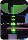
With a TTL laser, an optical inspection system can do magnified inspection and video measurement of edges and surface points, as well as laser scans of surface contours. The operator benefits because the imaging system shows where the laser will work. In fact, in some systems the laser can be used as a pointer. The bright laser spot strikes the part helping the operator to position it at the feature of interest. Here, a video measuring system with shared TTL laser shows how a long working distance provides access to internal features of a part. Source: Optical Gaging Products Inc.
More Than Imaging
In today’s manufacturing environment there is the need to do more in less time. One way to do that is to use multisensor metrology to get more measurements in a single setup. In a video measuring system, sharing the imaging optical path with a measuring laser is a good example. Such a through-the-lens (TTL) laser, adds the precision of point focus to an inspection system.With a TTL laser, an optical inspection system can do magnified inspection and video measurement of edges and surface points, as well as laser scans of surface contours. The operator benefits because the imaging system shows where the laser will work. In fact, in some systems the laser can be used as a pointer. The bright laser spot strikes the part helping the operator to position it at the feature of interest. This is much more user friendly than trying to find a specific feature while looking at a highly magnified image. Capable metrology software easily handles image and laser focus, scanning and processing of data points from both sensors. A touch probe can add greater versatility.
Optical inspection is a broad subject. All the configurations mentioned are being used somewhere in manufacturing every day. The choice of which method to use, is an important decision. Compromising on optical inspection can come with hidden future costs from rejects and customer dissatisfaction. The right inspection method leads to satisfied customers. Q
Quality Online
For more information on optical inspection, visit www.qualitymag.com to read the following articles:“Detect Defects Optically”
“Find the Right Optical Option”
“Sorting Through Optical Options”
Tech Tips
Looking for a reprint of this article?
From high-res PDFs to custom plaques, order your copy today!


