Improve Shop Floor Gaging with Ultrasound
Ultrasonic gaging can stand up to harsh shop floor environments and effectively get the job done.

New technology broadcasts ultrasound waves and receives their return signal through air, unlike most ultrasonic systems. These transducers differ from some other ultrasound devices in that they do not use oscillating crystals to generate sound waves. Rather, they use a unique method to vibrate a thin film at very high frequencies. Sound waves allow their transducers to be positioned some distance (standoff) from their target. Gage heads equipped with these transducers can be used at distances of 0 to 4 inches from their target if high accuracy is required, but as far away as 12 to 24 inches if lesser accuracy is needed. These devices tend to be rugged, resistant to the harsh environments of industrial shop floors and effective in measuring transparent materials.
By measuring the return signal in a manner similar to sonar or radar, this technology can be used for long standoff distance measurements, thickness measurements, total indicator readings (TIR), height measurement and other metrology applications.
The nature of the emitted beam of sound also has unique characteristics that are beneficial to some metrology applications, including the measurement of transparent objects. Unlike laser sensors, ultrasound reflects off glass and Plexiglas.
Ultrasound technology has been used in nondestructive testing (NDT) for many years. In most applications, such as thickness measurement, it requires contact between the probe and target, often with a gel placed between them. Sound waves carry through the target and return a signal according to tuned parameters. By contrast, this noncontact gaging technique lends itself to other applications. A sound wave will not penetrate materials but reflect off them. It will give an accurate and repeatable distance measurement on a solid target from as far away as 24 inches. Accuracies to within 0.0001 inch or better can be achieved from a distance of up to 4 inches, while accuracy diminishes as the standoff distance increases. Even so, at a range of 12 to 24 inches accuracy is better than 0.1% of standoff distance. It also will measure distance to textured surfaces with extremely high repeatability.

However, film-generated sound waves have a number of unique characteristics that make them useful in other situations. Sound waves are emitted from the transducer head in a narrowly expanding cone with a half angular beam width of 1.5 degrees. The transducer acts as both transmitter and receiver, and records the return of the first wave to bounce back and strike any part of the transducer face, which also acts as the receiver.
This is an inherent design feature, together with the fact that at the frequencies used, targets become specular (mirror-like) reflectors, meaning the angle of incidence of the transmitted sound wave is equal to the angle of reflection of the sound wave. Energy transmitted outside of the transducer spot is specularly reflected off into space and not received. Returning energy from spurious reflectors will arrive after the target and not trigger the target timer.
The speed of sound varies as air temperature varies. This is a major reason why ultrasound has not been used more often in accurate measurement gages. Even at the frequencies that film uses, a measurement made at a distance of 4 inches will vary by more than 0.2 inch if the environmental temperature changes by 38 F. This is not unusual in a manufacturing plant, between the hot part of the day and the cool part of the night.
Film eliminates this error, together with any other error caused by variations in air density by an external reference target integral to the transducer. Each time the film samples, up to 125 samples per second, the reference target location is measured. If the reference changes, a correction is applied to the target data, eliminating all errors caused by variations in air temperature and density. To ensure that the ambient conditions are the same at the surface, the reference target and the target to be measured, each system includes a fan that blows a laminar air stream to stabilize air temperatures in the beam path.
When used on an outer diameter (OD) measurement, the transducer responds to the signal returning from the nearest part of the target as if it were a broad faced measuring anvil. Signals that are not relevant to the measurement are reflected away.
This characteristic can be useful when forming or focusing the beam. By deflecting part of the signal, the beam can be shaped or focused onto a target or through an aperture. Signals can be directed so that they do not return to the receiver. For example, part of the signal can be deflected while the rest of the beam is directed down a blind hole so as to determine depth without returning off the outer land of the bore hole to give a false signal.
Similarly, when used on a concave surface, such as an inner diameter, the sensor responds to the signal returning from the furthest part of the target because signals striking other parts of the curved inner surface will be reflected away from the sensor. A direct return signal will only bounce back from that part of the wall that is perpendicular to the sensor. Film systems also include an alternative programmable “ignore” function that can, for example, look at depth or height while ignoring intermediate surfaces.
Because the signal beam is expanding from a broad, 30-millimeter face, it can strike a broad area of the surface but only receive that part of the signal that bounces straight back. Thus the sensor can be off center inside a bore yet still receive a signal from the important, most distant point or nearest point when measuring ODs. Consequently, film transducers, unlike transducers such as linear variable differential transformers (LVDTs), digital probes and air gages, can be somewhat forgiving as to position in relationship to the center of the target.
With suitably precise alignment of reflectors, signals also can be turned at right angles, with the return signal also being reflected back to the sensor. Thus the sensor can “see” around a corner.
The right-angled reflector approach also can be used to measure diameters of curved target surfaces. In addition, in extremely dirty environments it can be useful to include a 90-degree reflector on any sensor mounted below the work so as to prevent debris from falling on the sensor face.
Conventional sound waves produce an envelope of oscillations that increase and decrease with the smallest of environmental changes. Measuring distance and thickness using sound requires some algorithm to measure time of flight and convert time into distance. This measurement requires a starting point, when the sound is generated, and a stopping point, when the sound is returned from the target object or material. The starting point of the sound wave can be when a switch or gate is closed. The stopping point is much more difficult. There can be 50 or more cycles or oscillations in the waveform envelope, deeming the sound wave to be ambiguous.
In a real world environment, the envelope of sound cycles is a moving target, even though the target is stationary. This is caused by the effect of variations in air density and temperature slightly altering the time of flight of each cycle. The cycles will then constructively or destructively interfere with one another. The result is that cycle number n becomes cycle number n+1 or the reverse. Typical pulse echo systems trigger on the beginning of the return wave. If the return time is even off by one cycle, the measurement will be in error by 0.3 inch, depending on frequency. In addition, conventional sound systems operate at 40 to 50 kilohertz, making them vulnerable to naturally occurring sounds such as air lines, saws, motors and electric welding.
Film eliminates the ambiguity problem by using an extremely low mass film to propagate a sound wave. Film mass is so close to air that it couples to air well, eliminating the “ringing” of conventionally produced sound waves. Instead of 50 or more cycles in the envelope, it has two to three very fast rise time pulses. The system uses an unambiguous sound wave, at a much higher frequency. Because this sound wave is unambiguous, it can use a zero crossing technique to accurately measure time of flight or distance. This method removes any chance of error by electronically triggering on a set of events to ensure that only the correct part of the returned wave is used for measurement.
To qualify as an accurate return from a target, the receiver comparator must see a negative transition, a positive transition above a threshold voltage, then a negative transition through a zero crossing. Because of the steepness of the waveform, or high frequency, and low noise receivers, the stopping point of the timer counter is essentially a vertical line crossing a horizontal line, giving pinpoint accuracy. Another reason why these gages operate at more than five times the frequency of conventional systems is noise immunity. There are no naturally occurring noises above 100 kilohertz; It operates at between 200 to 250 kilohertz.
Yet another benefit to producing an unambiguous sound wave is that the sound wave also is used to detect and measure angular alignment of the sensor to the target surface. When making a measurement of distance or thickness to a surface, it is necessary for the sensors to be normal or perpendicular to the surface. If this is not the case, the measurement will not be accurate. This is true for micrometers and other forms of contact measurement and lasers. The system actually measures the angular alignment or misalignment by measuring its own waveform. This provides an electronic means of mechanically adjusting alignment and an on-line, real-time method of knowing if the measurements being reported are accurate. This is particularly critical if there is any case of the gaging fixture being knocked out of alignment by product transfer or some other event.
Until recently, ultrasound has not been used to make accurate gaging measurements. However, it is able to achieve accurate measurements because of the improved beam former, special gating to eliminate spurious echoes, unambiguous sound pulse, high frequency to eliminate ambient noise interference, automatic correction for thermal error and laminar air flow to condition measurement air temperature and density. NDT
Until recently, ultrasound has not been used to make accurate gaging measurements.
However, ultrasound is able to achieve accurate measurements because of the improved beam former, special gating to eliminate spurious echoes and unambiguous sound pulse.
Ultrasound also offers high frequency to eliminate ambient noise interference and automatic correction for thermal error.
New technology broadcasts ultrasound waves and receives their return signal through air, unlike most ultrasonic systems. These transducers differ from some other ultrasound devices in that they do not use oscillating crystals to generate sound waves. Rather, they use a unique method to vibrate a thin film at very high frequencies. Sound waves allow their transducers to be positioned some distance (standoff) from their target. Gage heads equipped with these transducers can be used at distances of 0 to 4 inches from their target if high accuracy is required, but as far away as 12 to 24 inches if lesser accuracy is needed. These devices tend to be rugged, resistant to the harsh environments of industrial shop floors and effective in measuring transparent materials.
By measuring the return signal in a manner similar to sonar or radar, this technology can be used for long standoff distance measurements, thickness measurements, total indicator readings (TIR), height measurement and other metrology applications.
The nature of the emitted beam of sound also has unique characteristics that are beneficial to some metrology applications, including the measurement of transparent objects. Unlike laser sensors, ultrasound reflects off glass and Plexiglas.
Ultrasound technology has been used in nondestructive testing (NDT) for many years. In most applications, such as thickness measurement, it requires contact between the probe and target, often with a gel placed between them. Sound waves carry through the target and return a signal according to tuned parameters. By contrast, this noncontact gaging technique lends itself to other applications. A sound wave will not penetrate materials but reflect off them. It will give an accurate and repeatable distance measurement on a solid target from as far away as 24 inches. Accuracies to within 0.0001 inch or better can be achieved from a distance of up to 4 inches, while accuracy diminishes as the standoff distance increases. Even so, at a range of 12 to 24 inches accuracy is better than 0.1% of standoff distance. It also will measure distance to textured surfaces with extremely high repeatability.
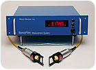
These transducers differ from some other ultrasound devices in that they do not use oscillating crystals to generate sound waves. Source: Albion Devices
Applications
In metrology applications it is important to know that air-propagated sound waves will reflect off liquids, so targets must be dry. Attempts to measure a critical diameter on a coolant-wetted work piece could lead to inaccuracy because the sound waves will reflect from the surface of the coolant rather than penetrate through the liquid to the solid material below.However, film-generated sound waves have a number of unique characteristics that make them useful in other situations. Sound waves are emitted from the transducer head in a narrowly expanding cone with a half angular beam width of 1.5 degrees. The transducer acts as both transmitter and receiver, and records the return of the first wave to bounce back and strike any part of the transducer face, which also acts as the receiver.
This is an inherent design feature, together with the fact that at the frequencies used, targets become specular (mirror-like) reflectors, meaning the angle of incidence of the transmitted sound wave is equal to the angle of reflection of the sound wave. Energy transmitted outside of the transducer spot is specularly reflected off into space and not received. Returning energy from spurious reflectors will arrive after the target and not trigger the target timer.
The speed of sound varies as air temperature varies. This is a major reason why ultrasound has not been used more often in accurate measurement gages. Even at the frequencies that film uses, a measurement made at a distance of 4 inches will vary by more than 0.2 inch if the environmental temperature changes by 38 F. This is not unusual in a manufacturing plant, between the hot part of the day and the cool part of the night.
Film eliminates this error, together with any other error caused by variations in air density by an external reference target integral to the transducer. Each time the film samples, up to 125 samples per second, the reference target location is measured. If the reference changes, a correction is applied to the target data, eliminating all errors caused by variations in air temperature and density. To ensure that the ambient conditions are the same at the surface, the reference target and the target to be measured, each system includes a fan that blows a laminar air stream to stabilize air temperatures in the beam path.
When used on an outer diameter (OD) measurement, the transducer responds to the signal returning from the nearest part of the target as if it were a broad faced measuring anvil. Signals that are not relevant to the measurement are reflected away.
This characteristic can be useful when forming or focusing the beam. By deflecting part of the signal, the beam can be shaped or focused onto a target or through an aperture. Signals can be directed so that they do not return to the receiver. For example, part of the signal can be deflected while the rest of the beam is directed down a blind hole so as to determine depth without returning off the outer land of the bore hole to give a false signal.
Similarly, when used on a concave surface, such as an inner diameter, the sensor responds to the signal returning from the furthest part of the target because signals striking other parts of the curved inner surface will be reflected away from the sensor. A direct return signal will only bounce back from that part of the wall that is perpendicular to the sensor. Film systems also include an alternative programmable “ignore” function that can, for example, look at depth or height while ignoring intermediate surfaces.
Because the signal beam is expanding from a broad, 30-millimeter face, it can strike a broad area of the surface but only receive that part of the signal that bounces straight back. Thus the sensor can be off center inside a bore yet still receive a signal from the important, most distant point or nearest point when measuring ODs. Consequently, film transducers, unlike transducers such as linear variable differential transformers (LVDTs), digital probes and air gages, can be somewhat forgiving as to position in relationship to the center of the target.
With suitably precise alignment of reflectors, signals also can be turned at right angles, with the return signal also being reflected back to the sensor. Thus the sensor can “see” around a corner.
The right-angled reflector approach also can be used to measure diameters of curved target surfaces. In addition, in extremely dirty environments it can be useful to include a 90-degree reflector on any sensor mounted below the work so as to prevent debris from falling on the sensor face.
This system uses an unambiguous sound wave, at a much higher frequency. Because this sound wave is unambiguous, it can use a zero crossing technique to accurately measure time of flight. Source: Albion Devices
Unique Sound Wave
For many years it was not considered possible to make accurate distance and thickness measurements using air-coupled ultrasound. A primary reason for this was the nature of sound waves. Air-coupled sound waves generated by conventional means were deemed ambiguous whether produced by speaker, piezoelectric crystal, voice or any other means.Conventional sound waves produce an envelope of oscillations that increase and decrease with the smallest of environmental changes. Measuring distance and thickness using sound requires some algorithm to measure time of flight and convert time into distance. This measurement requires a starting point, when the sound is generated, and a stopping point, when the sound is returned from the target object or material. The starting point of the sound wave can be when a switch or gate is closed. The stopping point is much more difficult. There can be 50 or more cycles or oscillations in the waveform envelope, deeming the sound wave to be ambiguous.
In a real world environment, the envelope of sound cycles is a moving target, even though the target is stationary. This is caused by the effect of variations in air density and temperature slightly altering the time of flight of each cycle. The cycles will then constructively or destructively interfere with one another. The result is that cycle number n becomes cycle number n+1 or the reverse. Typical pulse echo systems trigger on the beginning of the return wave. If the return time is even off by one cycle, the measurement will be in error by 0.3 inch, depending on frequency. In addition, conventional sound systems operate at 40 to 50 kilohertz, making them vulnerable to naturally occurring sounds such as air lines, saws, motors and electric welding.
Film eliminates the ambiguity problem by using an extremely low mass film to propagate a sound wave. Film mass is so close to air that it couples to air well, eliminating the “ringing” of conventionally produced sound waves. Instead of 50 or more cycles in the envelope, it has two to three very fast rise time pulses. The system uses an unambiguous sound wave, at a much higher frequency. Because this sound wave is unambiguous, it can use a zero crossing technique to accurately measure time of flight or distance. This method removes any chance of error by electronically triggering on a set of events to ensure that only the correct part of the returned wave is used for measurement.
To qualify as an accurate return from a target, the receiver comparator must see a negative transition, a positive transition above a threshold voltage, then a negative transition through a zero crossing. Because of the steepness of the waveform, or high frequency, and low noise receivers, the stopping point of the timer counter is essentially a vertical line crossing a horizontal line, giving pinpoint accuracy. Another reason why these gages operate at more than five times the frequency of conventional systems is noise immunity. There are no naturally occurring noises above 100 kilohertz; It operates at between 200 to 250 kilohertz.
Yet another benefit to producing an unambiguous sound wave is that the sound wave also is used to detect and measure angular alignment of the sensor to the target surface. When making a measurement of distance or thickness to a surface, it is necessary for the sensors to be normal or perpendicular to the surface. If this is not the case, the measurement will not be accurate. This is true for micrometers and other forms of contact measurement and lasers. The system actually measures the angular alignment or misalignment by measuring its own waveform. This provides an electronic means of mechanically adjusting alignment and an on-line, real-time method of knowing if the measurements being reported are accurate. This is particularly critical if there is any case of the gaging fixture being knocked out of alignment by product transfer or some other event.
Until recently, ultrasound has not been used to make accurate gaging measurements. However, it is able to achieve accurate measurements because of the improved beam former, special gating to eliminate spurious echoes, unambiguous sound pulse, high frequency to eliminate ambient noise interference, automatic correction for thermal error and laminar air flow to condition measurement air temperature and density. NDT
Tech Tips
Looking for a reprint of this article?
From high-res PDFs to custom plaques, order your copy today!


