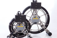
Remote Visual Inspection (RVI) is a term that characterizes inspection in areas that would otherwise be visually inaccessible. RVI enables an inspector to visually inspect these inaccessible areas with a tool that allows this to be done remotely and view otherwise invisible parts of a pipe, engine, gear box, or similar part or assembly. Without RVI, the inspector would have to completely disassemble the entire unit to see to the area of interest.
RVI has a very wide array of applications. They range from the simple, such as pipe blockage inspection, to the advanced, such as jet turbine engine inspection, which can include measurement. RVI plays a crucial role in these fields by improving the safety of equipment used by millions of consumers. In addition, RVI can save an enormous amount of resources by not requiring disassembly or modification of the equipment in order to adequately inspect by eye.
There are two important concepts that need to be considered with respect to RVI. The first corresponds to the “remote” aspect. One needs the ability to access the area of interest. The second corresponds to the “visual inspection” aspect. One needs the ability to effectively see and analyze the area of interest. There are a plethora of options, models, and accessories commercially available in the RVI field. However, they all serve at least one of the two main points of RVI.
Categories of RVI
There are three major categories of RVI equipment: rigid borescopes, fiberscopes, and videoscopes. While there can be considerable physical differences between the three categories, they all relate to the two core concepts of RVI. In order to access the area of interest, they all have what is known as an insertion tube. This is the part of the unit that the inspector inserts into the application until it is next to or near the area of interest. In order to effectively see and analyze the area of interest, each of the three has a unique way of gathering an image then transmitting it back to the user. A major consideration for being able to see the area of interest is having enough light to create an image, thus a majority of applications, because they tend to be interior to a machine, also require the introduction of external light.
Rigid Borescopes
Rigid borescopes are the simplest type of borescope. The fundamental components are essentially a hollow rigid tube and a lensing system. The light from the target travels through this tube to the inspector by way of a lens relay system. The image is focused and re-focused along the insertion tube in a straight path until it gets to the inspector by way of a small viewport.
As the name implies, the rigid borescope is not flexible. It is straight and rigid which means it requires line of sight to the area of inspection. It should be noted that only the insertion tube requires this line of sight. The far end of the insertion tube (the distal end) can have side-looking lensing so that the inspector can see what lies adjacent to as well as ahead of the insertion tube. The most advanced borescopes have included swing prisms to change the angle of view, and some have zoom capability where the lensing can be moved to change the magnification factor.
The rigid borescope will often be paired with a light source located next to the inspector. This light travels through the insertion tube by way of a fiber optic bundle situated next to the relay lens system. The light is then directed out next to the lensing so that the target is properly illuminated.
Cameras are also commonly used in conjunction with rigid borescopes. They can be attached to the viewport by way of a clamping lens adapter. However, these cameras are not typically suited for the industrial environments the rigid borescope is commonly used in. Plus, these cameras were generally designed for taking pictures and video from a different source.
Considering the two main concepts of RVI (accessing the target, seeing and analyzing the target), rigid borescopes are not very effective in being able to access the target. Once the smallest or slightest turn is required in order to access the area of interest, the rigid borescope is not able to access it. They are very good at seeing the target since only lensing separates the inspector from the target. Analyzing can become an issue due to interface of the camera accessories not generally lending themselves to this application.
Fiberscopes
The fiberscope retains the core concepts from the rigid borescope but adds length and flexibility to the insertion tube. The fiberscope transmits an image from the target to the inspector by way of a coherent fiber optic bundle. The fibers in the bundle are arranged in the same order on the end next to the inspector as they are on the end next to the target. The light from the image travels along the bends of each individual fiber and are organized in a mosaic fashion to recreate the image.
Thanks to the flexible nature of fiberscopes, the insertion tube can bend around turns and access areas that the rigid borescope cannot. The fiberscope also introduces the concept of articulation and interchangeable tip adapters. Articulation is simply the controlled curling of the last inch or so of the insertion tube in a 360 degree fashion. The articulation manipulates the end to look up, down, left, or right. The flexible insertion tube allows the inspector to better access the area of interest. The articulation can then perform fine movements in order to center the target in the image.
Some fiberscopes have interchangeable tip adapters, which are simply a lens that can be removed from the end of the insertion tube. This way the inspector can choose different directions to view, depths of field, and angles of the field of view. This can be done by simply changing the small tip adapter as opposed to switching the entire borescope as before.
The fiberscope is generally used in conjunction with a separate light source and camera in much the same way as the rigid borescope.
While the fiberscope has the benefit of being flexible, fiber optic bundles in general are brittle by nature. Therefore, due to the bending of the insertion tube, the fibers will begin to break over time. These will show up as black spots on the image since they are no longer capable of properly transmitting light. Fiberscopes also produce the lowest quality images. This is due to the nature of the fiber optic bundle. The image has a recognizable honeycomb pattern where each honeycomb is an individual fiber.
With regard to the two core concepts, fiberscopes are quite good at accessing an area of interest for inspection. They are not very good at allowing the inspector to see and analyze the target. The main reason for this is due to the inherent lower image quality fiberscopes have.
Videoscopes
Videoscopes are the latest evolution of RVI equipment. They have improved drastically since the mid 1990s when they were introduced. They maintain the flexible insertion, length, and the most advanced have interchangeable tip adapters that were introduced with fiberscopes, but instead of transmitting an image through a fiber optic bundle, they transmit an image through electrical means. At the target, an image is projected onto a camera chip. There are two types of camera chips, CCD (charged couple device) and CMOS (complementary metal oxide semiconductor). Generally CCDs are used in the most advanced system due to its faithful light sensitivity and greater image reproduction. The CMOS chips tend to be noisy and provide a lower quality image, but are much less costly and take much less power. They both convert the image into an electrical signal. This signal travels through the insertion tube by way of electrical wires. The robustness of the insertion tube is greater than rigid borescopes or fiberscopes since the electrical cables are inherently more robust.
The introduction of the camera chip enabled the introduction of a digital video signal to RVI. The video signal that is propagated through the insertion tube via the wires is turned back into an image on a monitor located next to the inspector. To do this, the signal must be manipulated and processed by a CPU located in the base unit that is commonly connected to the monitor. During this process, many enhancements and features can be added to the video. One of the first and most obvious features is that the videoscope itself is able to make and store images and video without the addition of any accessories. Other features include note taking, time and date stamping, and labeling of the area being inspected. An additional feature that can greatly improve a majority of inspections is the ability to remotely measure any defects that are seen on the image by using technologies such as stereo measurement.
The video is also enhanced when the digital signal is converted back into an image on the monitor. These include options such as brightness control, defect edge enhancement, noise reduction, and automatic white balance. A major enhancement that is possible with CCD technology is the ability to adjust gain. Raising the gain value for a CCD chip makes it more sensitive to light. This is important as many inspections are done in very dark environments. Advanced algorithms and enhancements such as a wider dynamic extended range can allow for gain adjustment of the darkest areas of an image, which could not be done with a borescope or fiberscope.
Another feature made possible through videoscopes is the use of LED light technology. The least costly LEDs tend to have a blue hue, but the most advanced scopes use warmer and more natural white light LEDs. LED technology is used in two methods. Some transmit LED through a light fiber which is efficient for shorter distances but can suffer from broken fibers if not well protected. The second method is to have micro LEDs installed at the very end of the scope. This can even be accomplished with interchangeable tips. This provides a great benefit for longer scopes and the best light efficiency.
Videoscopes have a great range of insertion tube technologies that allow various resistance levels. Some are as simple and a semi fixed aluminum or steel coil, others even are coated in hard polyurethane. The most advanced used in the inspection of jet engines are multi layered, extremely durable tubes consisting of steel coils, tungsten braids, resins and waterproofing materials. Different tube construction can allow for inexpensive replacement, or extremely damage resistant equipment.
The videoscope, with its long, flexible, and robust insertion tube, certainly allows easy access to the area of interest for an inspection. The high quality image created by the small but dense CCD chip, or the less costly CMOS, allows the inspector to see the target. The enhancements and features (specifically the stereo measurement option) greatly allow the inspector to also analyze the target.
Clearly, the videoscope has many more features and benefits not shared by the rigid borescope or fiberscope. However, they are generally more expensive than the fiberscope and rigid borescope making the latter two still relevant. Through these technologies, industries are able to economically and safely extend the life of equipment that runs our modern world.


