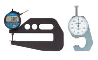
Thickness is a measure of coatings or films, such as the thickness of paint on metal, or the distance between the closest opposing surfaces of an object, such as the thickness of plywood. We will talk about noncontact, optical methods for measuring thickness and automating these measures with machine vision.
Coating Thickness
Thin, nearly transparent coating thickness can be measured using optical interference. Light waves reflected from the top and bottom of the coating interfere and so appear lighter or darker, depending on the light wavelength, the coating thickness, and the object’s indices of refraction. Monochromatic light produces light and dark stripes or fringes. White light produces colored fringes, as seen in a soap bubble, for example. Coating thickness is measured by counting the fringes, comparing the phase of the fringes, and the fringe contrast. There are many methods for converting these relative measures into absolute thickness measures.
Thicker (ten microns or more), nearly transparent coatings, such as conformal coatings on electronics, can be measured by using depth from focus. A microscope is focused on the substrate and then on the top surface of the coating and the difference in focus determines coating thickness. A confocal microscope, where only a single focal plane is illuminated and imaged, improves this method’s resolution. Triangulation, discussed below, can be used for even thicker coatings. Of course, there must be measurable reflection off of both coating surfaces.
Edge Thickness
In some cases measuring thickness along an object’s edge is sufficient, for example looking at sheet glass or plywood “edge on.” When the object is round or half-round, such as a bead of glue, width or diameter of the object is sometimes called its “thickness.” For these cases, standard machine vision caliper tools do an excellent job. These tools find edge-to-edge distances (thickness) where an edge is defined as a sudden change in image intensity.
Opaque Coatings
Opaque coatings can be measured by subtracting the height of the object before coating and the height (or depth) of the object after coating. Here height is a measure of perpendicular (normal) distance from the object surface to a reference plane. Measurement accuracy now depends on the sensor, on how well the substrate and subsequent coatings line up, and on having the substrate on the same flat surface before and after coating.
Thickness from Height
We can use height to measure thickness of objects such as film or plywood. A single sensor approach subtracts the height of a carrier, for example the surface of a guide roller, from the height of the object and carrier to get the height of the object. Accuracy is limited by variations in the carrier height, so some suppliers use additional sensors to measure this variation.
A dual sensor approach is better when both sides of the object’s thickness can be seen. Thickness is the absolute difference between the height measurements of sensors on either side of the object. For example, thin film material such as plastic film can be run between two line sensors that measure heights at hundreds of points across the film. Accuracy depends on having the dual sensors “caliper” corresponding points on either side of the object.
Here are two of the many methods for optically measuring height (or depth) to derive thickness. I picked these methods because they are common in production line quality control and because they are amenable to automation with machine vision.
Time of Flight and Amplitude Modulated Light
Height or distance can be measured by multiplying the time it takes for a pulse of light to reflect off an object by the speed of light. The accuracy of this lidar (light radar) depends on the accuracy of the timing clock. Because of its long range and expensive clock, lidar is commonly used in applications such as terrain mapping or measuring the distance to the moon, rather than in manufacturing.
Instead of sending pulses, we can amplitude modulate a beam of light and use the phase shift of the returned beam to measure distance or height. The method is something like interferometry, where the phase of the returned signal is detected by comparing or “mixing” it with the sent signal. The slow modulation makes a long wavelength signal and, as long as the object distance is within a wavelength, the distance measure is unambiguous. It is easier to generate an accurate modulation period than to time a returning lidar pulse.
Triangulation
Triangulation is the most common method for machine vision measurement of height or depth. A typical triangulation system shines a spot or line of light on an object and uses a camera to view that spot or line at an angle from the object surface perpendicular. Usually a laser is used for the light source because it can be tightly focused and a narrow band filter can be put over the sensor or camera to block ambient and incident light.
As the surface changes in height, the laser spot or line will shift up or down in the view of the camera. The shift in the spot or line viewed by the camera can be calibrated to the shift in height. The working range (heights that can be measured) and resolution of a triangulation system can be set by the distance between the light source and the camera and the camera angle.
Less common forms of triangulation include structured light, where a pattern of light is put down rather than a single spot or line, and stereo vision where the differences in object detail positions in two, separated camera views is used to compute depth. Structured light works well when the shifts in the viewed pattern do not overlap. Stereo vision (like our two eyes) requires part surface structure and so does not work well, or at all, on uniform surfaces.
An Example
High pressure oil pipelines are made from welded steel tubing and, for extra strength, the tubing is then wrapped in a spiral of sheet steel. The diameter of the tubing is considered to be constant and the quality control question is if the sheet steel is wrapped tightly and with some maximum gap between wrap cycles. The wrapping is inspected as the pipeline is made in the field.
After the pipe is welded, its surface smoothness is checked using triangulation with multiple lines of laser light. Then the wrapping is applied and a single laser line triangulation system measures the height of the wrapping to detect loose wraps and check for gaps between wraps or, even worse, overlap of wrapping material.
To add to the challenge of this application, the system must operate in temperatures that can exceed 110 degrees F.
In summary, measuring thickness can be a bit more complicated than you’d expect. However, by automating noncontact, optical methods for measuring thickness with machine vision you’ll be able to simplify the process.
References
General
Thickness Measurement
John C. Brasunas, G. Mark Cushman and Brook Lakew
In The Measurement, Instrumentation and Sensors Handbook CRC Press (1998)
Optical methods for distance and displacement measurements
Garry Berkovic and Ehud Shafir, Advances
in Optics and Photonics 4, 441–471 (2012)
Coating Thickness
http://en.wikipedia.org/wiki/Interferometry
Thickness from Height
http://www.ndc.com/en/Products/Laser-and-Optical-Gauges.aspx


