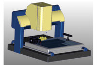
Multisensor coordinate measuring machines that combine vision, touch and laser sensors have been used in manufacturing quality control for nearly 20 years. Like most manufacturing technologies, Multisensor systems have evolved considerably over the years as the component technologies for motion control, optics, lighting and cameras have improved.
Many still recall the early days of multisensor systems when the primary sensor worked well, but the additional sensors—sometimes added almost as an afterthought—offered limited capability and poor accuracy.
TECH TIPSToday’s multisensor systems have advanced to the point that all sensors now offer full capability and accuracy. Limitations inherent in earlier designs have been removed through more careful integration of the sensors with the measuring axes. Improvements in the metrology software are the greatest enabler of comprehensive multisensor capability. |
Today’s multisensor systems have advanced to the point that all sensors now offer full capability and accuracy. Limitations inherent in earlier designs have been removed through more careful integration of the sensors with the measuring axes.
Improvements in the metrology software are the greatest enabler of comprehensive multisensor capability. Measuring software has evolved in ways that allow each sensor to be truly integrated and measure with consistent uncertainty at all times.
Along the way the economic benefits of multisensor measurement systems have become clear: reduced capital and calibration expenses, shorter learning cycles, added flexibility and convenience, and most important—lower overall uncertainty in the measurements.
To highlight the full range of capabilities of today’s multisensor measuring systems, let’s look at three types of parts and how their manufacturing processes have been improved by using multisensor measurement.
Femoral Implant
In Figure 1 we see a femoral implant being measured with a caliper. If only it were so easy! Orthopedic implants are among the most complex-shaped devices being machined today; there is simply no way to measure the critical dimensions and form of these parts with a single sensor system.
For starters, the highly polished surfaces of knee implants are extremely sensitive. Even casual contact by a tool or gage could damage the surface finish, causing friction that could lead to improper fit and ultimately pain in the patient receiving the implant. To measure these parts, a variety of noncontact or minimally invasive tools—vision optics, lasers or very light contact probing force—are needed.
More importantly, femoral implants consist of a series of curves controlled by profile tolerances, each of which are simultaneously constrained by the material condition of one or more datum features. These geometric dimensioning and tolerancing conventions enable the designer to specify the form of the part exactly, but make verifying the part a challenge. To properly measure this part, the measurement points must be collected, then fitted to the CAD model in their entirety in order to ensure all material conditions are properly evaluated. Data from tactile, scanning, laser and optical sensors needs to be integrated with the CAD model, and powerful software is needed to perform the GD&T evaluation.
Enter the modern multisensor system. A system with telecentric optics, through-the-lens laser, and a micro-scanning probe can measure the outside dimensions, profiles and curves without damaging the part, and compare the data directly to the CAD model.
The manufacturer of this part faced high re-work and scrap rates, in spite of careful machining, polishing and measurement. Compounding the issue were disputes about dimensional conformance between different measurement techniques.
Multisensor measurement solved the first problem, by accurately measuring the critical features without damaging the part. True multisensor software enabled the data to be fitted to the CAD model and applied the GD&T standards properly.
This combination enabled the manufacturer to eliminate disputes about measurement accuracy between different gages, and ultimately reduce the number of finishing steps needed to produce the part to customer specs. All of which reduced scrap and re-work costs substantially.
A Large Casting
Our next example is a large casting with a variety of machined surfaces, mounting holes and bearing ways on each of its four sides. This part has more than 50 discrete dimensions that must be controlled to ensure fit and function within the assembly it is part of. Many of these dimensions relate to datums on opposite or adjacent sides of the part. Ideally, the part would be measured in one set-up, without having to re-stage the part to enable measurement of all its surfaces.
While access and tolerance issues make a tactile scanning star probe (Figure 3) the ideal sensor for the bearing tracks, other features such as the small blind holes on the adjacent face are best measured using video, while surface flatness measurements on the mating surfaces are best made using a laser. The custom made flip fixture in this photo automatically indexes the part to present each side to the sensor array for measurement. This casting is a component in a complex assembly that relies on machined-in precision for the reliability of the overall mechanism. Thus, measurement is critical to the overall quality of the end-product.
For the maker of this part, multisensor measurement offered a number of benefits. Most significant was the time savings of being able to confirm all dimensions on one system, rather than having to program, stage and measure on several different systems, then combine and compare the data to determine if the part met spec. Another significant benefit is that the multisensor system offered the same uncertainty regardless of the sensor used.
Complex Machined Casting
In our third example, we see another complex machined casting—in this case, a hydraulic transmission housing. This part presents a challenge to measure in a single set-up. Not only are there dimensions along the outer stems and top flange, there are dimensions on the seal surface and spline more than six-inches deep inside the part. To access all these features in one orientation, long working distance optics and a LWD laser are needed to reach features at the bottom, as well as scanning probe capability to measure inside dimensions on the stems and interior profile.
Once again, the combination of scanning probe, laser and video measurement makes quick work of measuring this complex part. The laser quickly gathers a large pattern of data from the mating surface on the top flange. Flatness on this seal surface is critical. The scanning probe measures the interior profile in several locations, as well as the inside diameters of the in-flow and out-flow stems to calculate interior volume and flow rate characteristics. The long working distance laser also reaches to the boss on the inside of the spline for a flatness measurement, and long working distance optics quickly measure the gear teeth and ball bearing positions in the ball spline.
Each of these three examples illustrate the value inherent in a high quality multisensor measurement:
In all cases, it was possible to measure the entire part on one measuring system—saving the cost of buying and maintaining multiple measuring systems, and eliminating the differences in uncertainty between differing measurement technologies.
The range of sensors available enabled the key dimensions to be measured using the best sensor type for the feature without compromising efficiency or accuracy. Deployable and long working distance sensors help eliminate interference between sensors and minimize offsets that use up valuable measuring range.
The measuring software integrated the data from all sensors seamlessly, allowing all measurements to be performed in a single routine and compared directly to the part’s original CAD model, ensuring the most faithful confirmation of the design intent.


