Considerations for Precision Shaft Measurement
Selecting the best measuring solution for a complex shaft can be a confusing proposition.
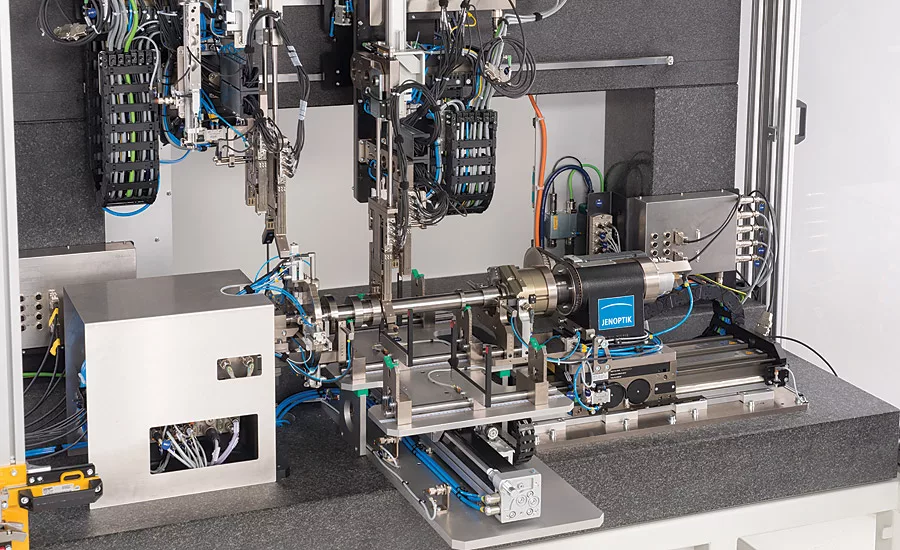
Jenoptik automatic crankshaft measurement systems are capable of measuring multiple part types randomly introduced on the fly, at production rates, with cycle times measured in seconds. This provides valuable data for process optimization. Source: Jenoptik
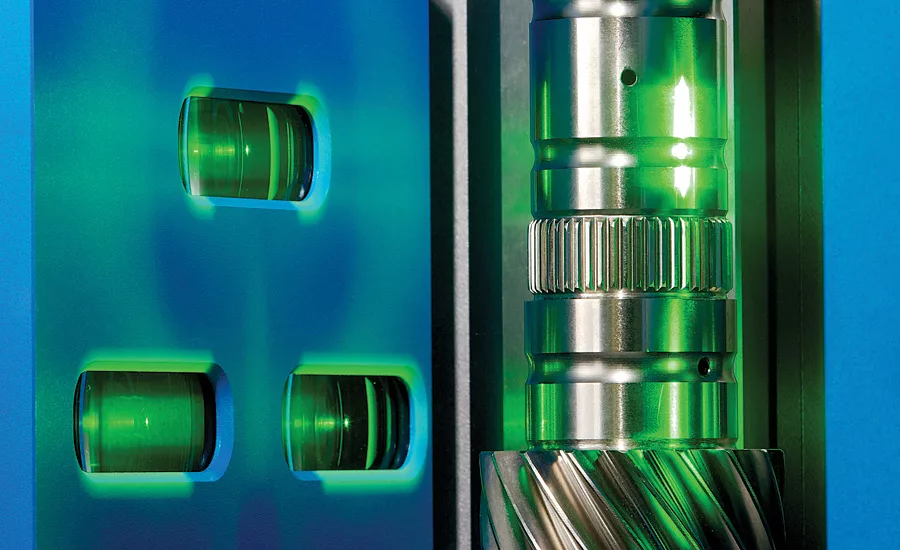
Noncontact optical systems can be benchtop, designed for operation on the shop floor, to large lab machines. The biggest advantages to optical technology is its flexibility and speed in evaluating almost any part type that will fit within the confines of system itself, as well as its ease of use when setting up these new part types. Source: Jenoptik
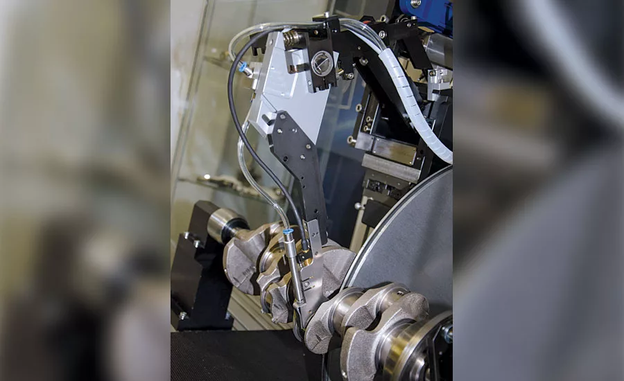
In-process gaging for grinding operations, such as on this crankshaft, are dedicated systems for measuring form, geometry, and roughness. This automatic system is capable of measuring at full machine speed and provides data used to adjust the grinding process to assure consistent quality production.
Source: Jenoptik
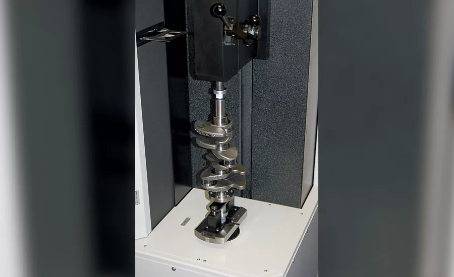
A traceable crankshaft journal form measurement machine automatically measures a wide range of journal characteristics from form and pitch to diameter, parallelism, cylindricity and more. Source: Jenoptik
Whether its in-line, off-line, in-process, or post-process, manufacturers are constantly searching for the best available measurement technology, and today’s metrology companies are stepping up to the plate to deliver.
Nowhere in the manufacturing world will you find this more self-evident than with the measurements taking place in the powertrain components of the modern day automobile, many of which are shaft-type precision parts. Injectors, pistons, connecting rods, turbo chargers, camshafts, crankshafts and more, are critical for ensuring optimal power and performance of the vehicle.
Tech TipsTwo important factors to consider when discussing shaft dimensional metrology are frequency of inspection and characteristic limits.
|
Of all those components, the heartbeat of the entire assembly is the crankshaft. Crankshafts can require inspection of an incredibly diverse set of dimensional characteristics, making it, from a technology standpoint, difficult to implement effective quality control.
Selecting the best measuring solution for a complex shaft can be a very confusing and frustrating proposition. To make the best decision, ask some of the following questions:
- What type of dimensional characteristics will require inspection? Are they diameters, lengths, widths, pin strokes, or taper?
- Where will the inspections take place? On the shop floor or in a metrology lab?
- Can the measurements be performed in-process or post process, either in-line or off-line?
- What are the production requirements (frequency of inspection)?
- Is it just one dimension, or 100% part inspection?
- What kinds of operator skills are necessary to perform the inspection?
- And last but not least: How flexible does the inspection equipment need to be?
New advances in technology are allowing gaging manufacturers to find innovative solutions for measuring crankshafts and other complex shafts. Here are a few fields that have seen noticeable improvement over the last decade:
PNEUMATIC
Dimensional pneumatic gaging is accurate, repeatable (0.1 micron), robust, and cost effective. Technological improvements in this field include lower air volume requirements, faster response times, built-in temperature compensation, and more.
Pneumatic gaging can deliver fast, accurate results time and again with very little to no maintenance. Measurement ranges vary based on whether it’s a low or high pressure system, but top of the line systems can deliver a measuring range of ±.080mm, delivering repeatable accuracy at tolerances as low as ±.0001mm. Typical applications for pneumatic gaging of crankshafts would mainly consist of post-process applications (both in-line and off-line systems).
CONTACT
Contact gaging comes in many varieties and has taken tremendous strides over the last decade in terms of accuracy and reliability. Pencil probes (or L.V.D.T. probes) are the mainstay of this type of measurement along with various versions of contact tips (ruby, carbide).
Typically, contact gaging has been much more susceptible to environmental conditions than pneumatic systems, especially very dirty environments like on in-line measurement systems. Technological improvements here have led to more robust devices that are much more capable than their predecessors, delivering high accuracy and reliable repeatability even under adverse conditions.
In addition, altering contact designs allows for extremely flexible shaft measurement machines that can perform form, surface finish, and other demanding characteristic evaluations. Typical applications for contact gaging of crankshafts would be post-process (in-line, off-line, and point-of-use systems) and in-process (size control for journals, lobes, for example).
OPTICAL
The most recent technology to gain acceptance for shaft dimensional inspections are optical systems. The improving capability of optical measurement systems over the last few years has led to increasing popularity of this type of technology. Better lighting systems, high resolution sensors, and improved software has led to a marked increase in the overall capability of these systems to perform industry leading evaluations on a highly diverse group of parts.
The single biggest advantage to optical technology is its flexibility in evaluating almost any part type that will fit within the confines of the system itself, as well as its ease of use when setting up these new part types.
Simply load the part into the gage, perform a complete part scan with the system optics and then select locations on the scanned image for the evaluations you want to perform. Once all the evaluations have been assigned to the part, select start and the entire part can be inspected in a matter of a few seconds. Applications for optical gaging would exclusively consist of post-process systems, both in-line and off-line.
SUB SYSTEMS
The final area that has seen noticeable improvement over the last few years are the supporting systems like linear actuators, motors, cameras, slides, and more. CNC improvements alone have led to the development of fully automated in-line systems that can measure parts on the fly with no (or little) changeover required. Imagine being able to measurement multiple crankshafts, introduced randomly to the system, with no changeover required. Materials technology and engineering advances have led to increases in system longevity, environmental resistance, and more.
CHARACTERISTICS
Two other important factors to consider when discussing shaft dimensional metrology are frequency of inspection and characteristic limits. Frequency of inspection is critical in determining where in the process (location) the evaluation will occur and what type of technology will be used (pneumatic, contact, or optical).
If you’re inspecting 100% of part production and you produce hundreds of parts an hour, then an in-line system might be the only way to go. If only inspecting every 100th part, then an offline system might be the best bet. Frequency also determines the best technology since having to inspect a ±.010mm tolerance every five seconds would best be handled by pneumatic technology vs. the same tolerance being inspecting every 20 seconds which might best be handled using contact technology.
Characteristic limits (i.e. tolerances) probably play the single largest role in determining the time, place, frequency, and technology used to evaluate any given part. If the characteristic limit is ±.010mm, then a pneumatic system might be advisable. If the limit involved is ±.080mm, then a contact system might be all that is needed. In the end, tolerance limits play a significant role in selecting the proper technology in any given inspection.
CONCLUSION
These represent just some of the options for dimensional technologies, so only begin to address the application of each technology to a specific need. To obtain a best practice solution you will need to consult with your preferred gage system supplier, remembering to bring with you at a minimum the answers to these questions along with an open mind. In the end, selecting the right time, place, frequency, and technology will help you control your part quality efficiently, effectively, and most important economically. Q
Looking for a reprint of this article?
From high-res PDFs to custom plaques, order your copy today!


