Understanding the power and complexity behind a CMM allows the operator to maximize productivity.
Unleash Your CMM’s Potential
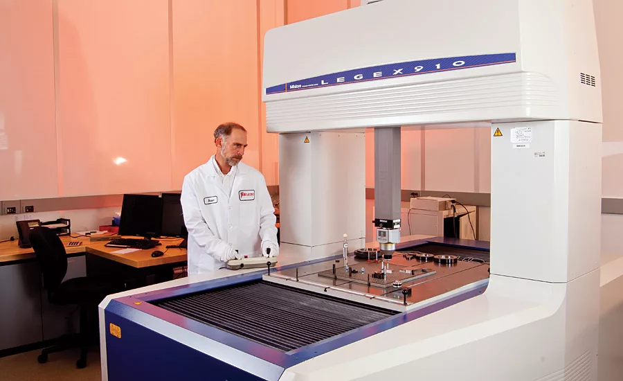
At the Mitutoyo America Calibration Lab (Aurora, IL), CMMs measure with an uncertainty of only a few millionths of an inch. To achieve that accuracy takes an extreme understanding of the machine, its calibration, the probe system and the influence of temperature. Source: Mitutoyo
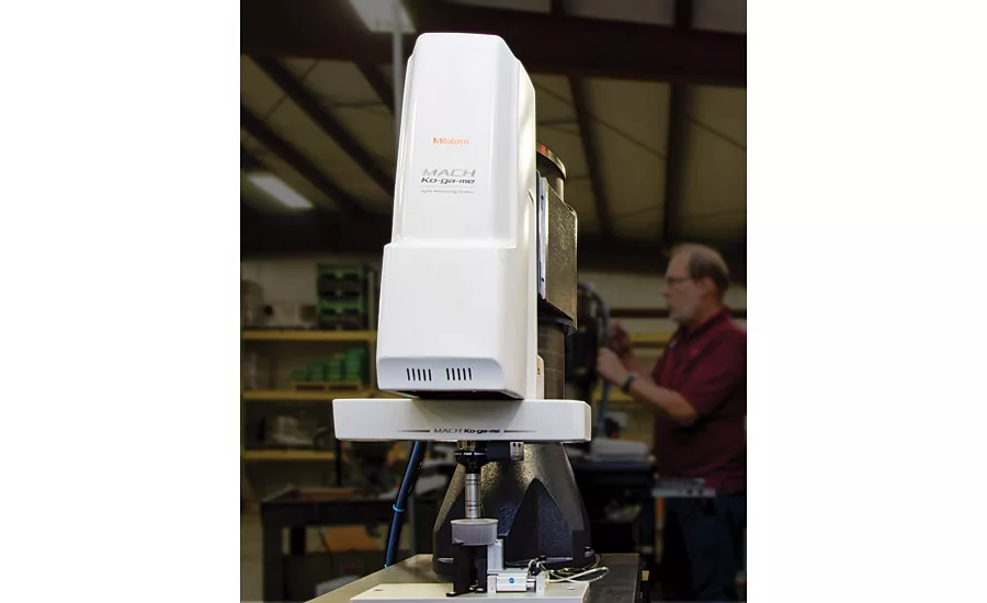
CMMs are routinely found on the shop floor, often running in automated cells. Source: Mitutoyo
CMMs are routinely found on the shop floor, often running in automated cells. Source: Mitutoyo
Temperature Compensation
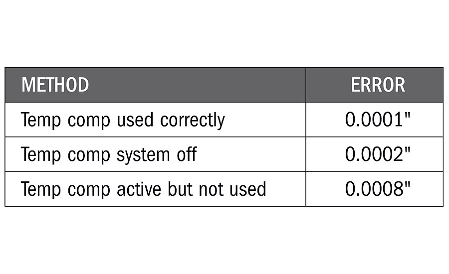
Many CMMs have built-in temperature compensation systems that include workpiece temperature sensors. These systems should be either used correctly or completely turned off by the CMM manufacturer. If they are simply not used, but still on, then unexpectedly large errors may arise. The table below shows a case where a 20” length is measured on a steel part at 75 F.
CMM Accuracy Table
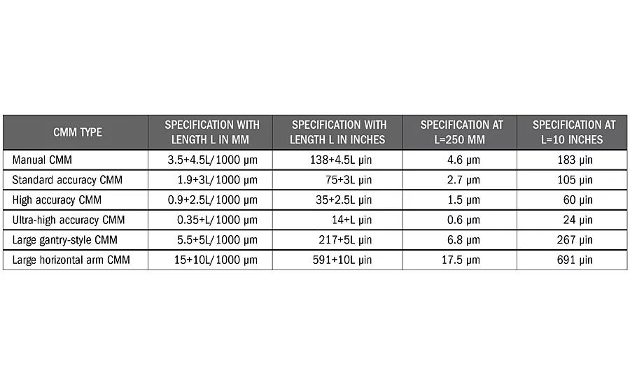
The accuracy of CMMs are specified and calibrated in accordance with ISO 10360-2. The most important specification, which covers linear and volumetric length measuring accuracy, is the E-test. The specification was originally just called E (in 1994), but in later editions of the ISO 10360-2 standard, the specification was called MPEE (2001) or E0,MPE (2009), where MPE is the maximum permissible error. The table below shows typical CMM manufacturer stated specifications for the E-test based on the type of CMM. When used properly, in the permissible environment, these specifications represent the maximum error of the CMM when measuring length.
For more than 50 years, coordinate measuring machines (CMMs) have been improving measurement productivity and quality. The power of CMMs has made many complex inspection tasks seem almost trivial. With this much measurement capability, is it possible operators are taking their CMMs for granted?
CMMs often are expensive, with sophisticated software and complicated accuracy specifications, yet many CMMs are successfully and efficiently used daily by operators, even those with limited knowledge of their CMM. As with much of modern technology, the daily use of CMMs becomes easier, while the level of knowledge needed to properly support the technology can become quite high. Let’s take a closer look at some of the key issues to help operators better understand and use their CMMs.
Introduced in the 1950s, the first CMMs were manual inspection instruments equipped with tapered cylinder probes that could be used to quickly measure the distance between holes in two dimensions. The goal of these early CMMs was to reduce hours of layout inspection time to just a few minutes. While still having similarities to the original CMMs, today’s modern CMM comes in so many different styles that the term coordinate measuring systems, not machines, is being used with more frequency. Traditional three-axis CMMs are still quite popular, but articulating arms, laser trackers, optical scanners, X-ray, advanced probing sensors, as well as high-speed in-line measuring systems and other technology for 3-D measurements continue to grow and change the traditional CMM market.
CMM Calibration
The advanced technology on the CMM has made understanding the accuracy of CMM measurements complicated. When we think about and manage the quality of any measuring process, we often focus on two separate issues: one being the accuracy of the measurement equipment, and the second being the accuracy and repeatability of the measurement process. The accuracy of the measurement equipment is frequently managed through proper calibration and verification against the original manufacturer specifications. The situation is the same for CMMs, but calibration is more complex.
The calibration of something simple, such as a gage block, is easy to understand. It is a length standard, and therefore, you calibrate the length. For calipers or micrometers, which measure lengths, you calibrate them for measuring lengths. CMMs often have multiple axes of motion, diverse probing sensors and come equipped with software to measure almost anything. Unlike the gage block or caliper, you cannot separately calibrate a CMM for each measuring task it performs, as that would not be economically practical. It is also not very useful to separately calibrate the mechanical components of a CMM, such as the accuracy of an individual measuring axis or the squareness between axes, because all the components work together and their influence on measurement results is complicated.
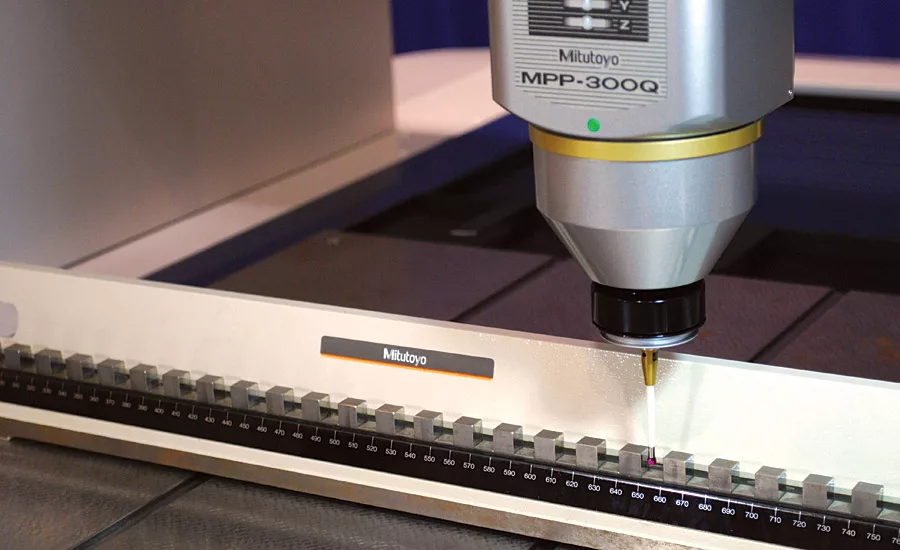
CMMs, instead, are calibrated by performing a series of length measurements across the measuring volume of the CMM. Well-documented standardized test procedures have been available since the mid-1980s, the latest of which is the international standard ISO 10360-2:2009, which was adopted in the United States as ASME B89.4.10360.2. The primary test is simply known as the E test, where E stands for error of indication. The test involves making 105 different length measurements across the measuring volume and in various orientations, and then comparing the test values to the manufacturer’s stated specification. The most common reference standard used for CMM calibration is a step gage, which is not unlike a series of different length gage blocks. Other reference standards, such as a laser interferometer which is popular for large CMMs, are also permitted per the latest ISO 10360-2 standard.
A CMM calibration following the ISO and ASME standards is an overall system verification. If the test fails conformance, then adjustments may be needed. To complete the adjustments, additional measurements, such as the squareness between two axes, may need to be measured and corrected. If the test passes, then the CMM operator has confidence in the overall general accuracy of the CMM; however, as CMMs can be used for so many different tasks, consideration must be given to understanding the additional errors due to the specific use of the CMM.
CMM Repeatability
When assessing the quality of measurement processes, it is fairly common to complete some type of repeatability study. In many industries this is called the gage repeatability and reproducibility study, or GR&R. The purpose of the repeatability study is to look for variation in the measurement process, over a relatively short time period, which complements the long-term evaluation of the equipment calibration. Any GR&R or repeatability study needs to be designed to properly evaluate likely sources of variation, for example, errors in the measurement process. For traditional manual-operated measuring equipment, operator skill and the interaction between the operator and measuring equipment is important, and sometimes the most dominant, sources of error. For fully automated CMMs, these error sources may disappear.
For any automated measuring process, the repeatability may appear quite small due to the design of the repeatability study not being sensitive to the real sources of variation. For CMMs, the study should include the influence of calibrating the probing sensors (sometimes called probe tip qualification) along with considering the influence of the distribution and number of measurement points taken, for example, the sampling strategy. Both of these error sources are specific to a unique measuring task and are generally not well covered in the calibration of the CMM. If performing a GR&R study, the reproducibility can be changed from studying different operators to instead studying different probe-tip calibrations.
Temperature Compensation
Many CMMs today come equipped with built-in temperature compensation systems. These temp comp systems can do an amazing job of compensating and correcting large thermal errors associated with either the CMM or the measured part not being at the standard reference temperature of 20 C (68 F). However, if a temp comp system is not being used correctly, these systems can introduce extremely large errors.
Consider a situation where a CMM operator decides not to use the system by ignoring the workpiece sensors or setting the workpiece coefficient of thermal expansion to zero. The operator may be thinking he will instead follow traditionally good measurement practice of thermally “soaking out” the measured part on the measuring equipment to bring them to the same temperature, and therefore, not need to correct the thermal errors. While this approach has worked for decades on traditional measuring equipment without temp comp, the operator may be unaware that the temp comp system is still actively working to correct the CMM, and only the CMM, to 20 C, while the workpiece is not being corrected. By ignoring the use of the workpiece sensors, a temperature differential is created that could result in significantly large and unknown errors.
For CMMs with temp comp, the best approach is to place the workpiece temperature sensors on the measured part. If that approach is not convenient, then the temperature sensors could be placed near the measured part, for example, integrated into some fixture holding the part. In this manner, a relatively accurate measurement of the part temperature can still be made even if the temperature sensors are not in contact with the part. If there is no plan to use the workpiece temperature sensors, then the entire system should be turned off, which can usually only be done by a service engineer from the manufacturer of the CMM.
GD&T Issues
The measuring software on CMMs introduced the first widespread use of digital and computational measuring methods. CMM software has functions and buttons that are based on the symbols and meanings in the geometric dimensioning and tolerancing (GD&T) standards such as ASME Y14.5. While this has introduced much debate among experts as to what is a “correct” measuring method (if one even exists), the more practical problem for CMM operators is that different methods or software approaches can significantly change the measurement results. Two different CMMs, both operating within specification and with sufficient repeatability, can give radically different results due to choices made by the operator or in the software.
The developers of CMM software would love to fix a single best approach to measuring any particular GD&T tolerance, and some companies will even claim their measuring software “complies to ASME Y14.5,” but that is unfortunately impossible and incorrect. GD&T standards such as ASME Y14.5 have rules for defining workpiece design, not for how to measure, so ASME Y14.5 is not a standard for which any measurement has ever, or will ever, comply. In addition, there is always a purpose behind why every measurement is made, and that purpose must be taken into consideration when determining the best measurement method. Developers of CMM software need to provide an array of tools that can satisfy the needs of many different users, as well as have application engineers who provide the necessary guidance to their customers.
The best measurement method for one operator may be very different than that of another, even when measuring similar parts or tolerances. Measurement productivity, costs, legal risks and other issues must be balanced appropriately to find the best solution. Good dimensional measurement planning cannot be overlooked, even though the button on the CMM makes it look easy. Measurement planning is probably the biggest implementation issue all CMM operators must manage. The hardware and software options in CMMs today are vast and powerful, and companies need to develop best operating practices to ensure all implementation risks are being managed. A good guide for measurement planning is the U.S. standard, ASME B89.7.2-2014 Dimensional Measurement Planning.
CMM operation in the future will be very different than today. Advanced CMM software is already available that allows for measurement programs to be generated in seconds based on digital part models. CMM programmers in the future will not have to give much thought on how to measure a specific part, but they will need to understand metrology and tolerancing principles to develop best practices and measurement rules that can then be deployed for all CMM measurements. CMM technology is continuing to advance with increasing benefits in improved accuracy, additional capability and reduced measurement time. For CMMs, as for any technology we use, as the tools become more advanced, the type and level of support must also become more advanced.
Looking for a reprint of this article?
From high-res PDFs to custom plaques, order your copy today!


