3D printing is rewriting the manufacturing rulebook
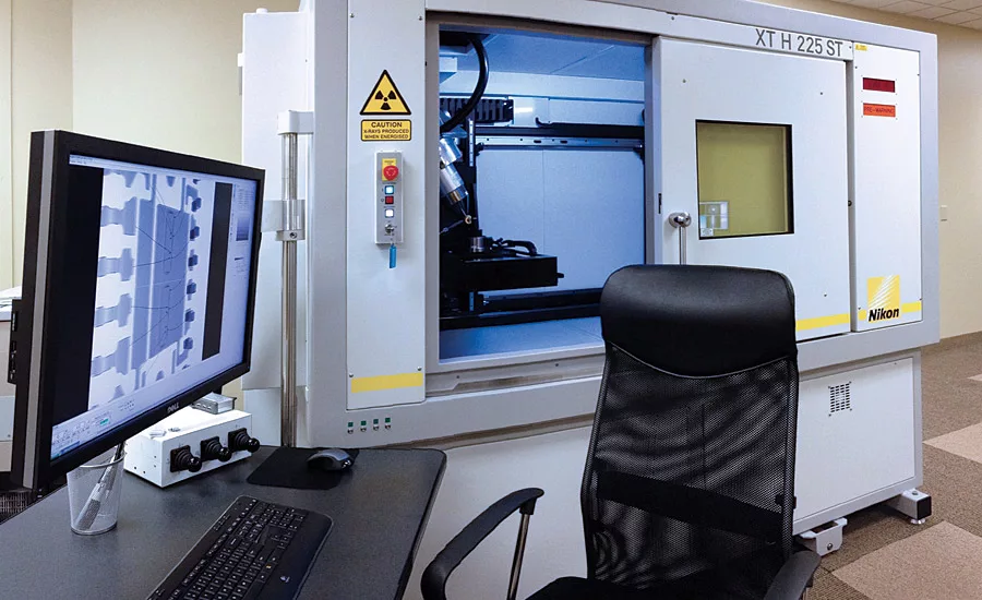
Nikon Metrology XT H225 ST X-ray CT setup. Source: Nikon Metrology
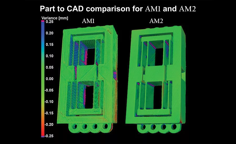
Part-to CAD comparison for FDM and STL versions of the same part. Source: Nikon Metrology
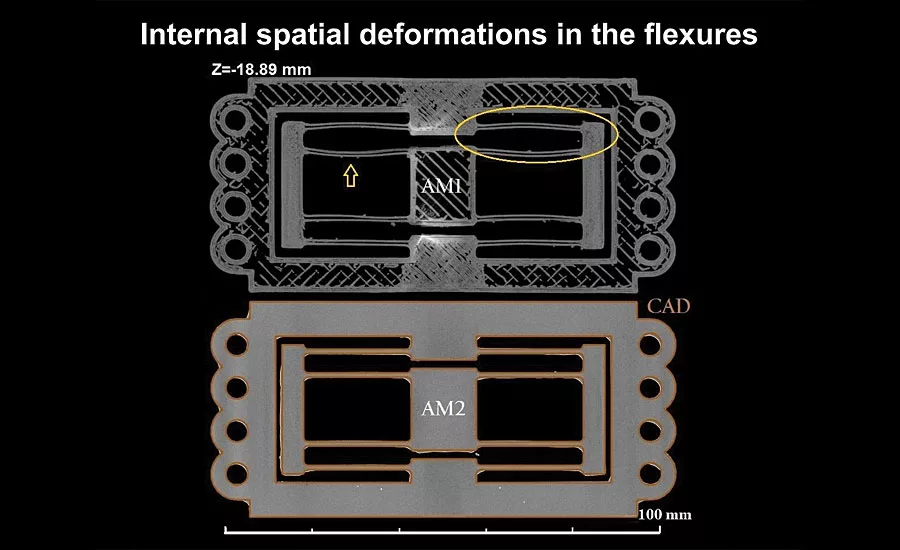
Flexure deformations revealed by CT scans. Source: Nikon Metrology
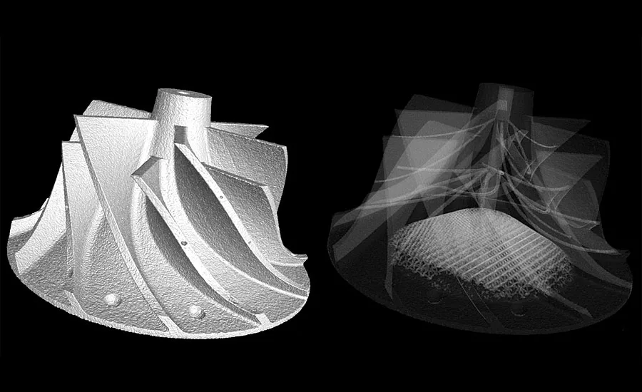
Scans can reveal external and internal features for checking. Source: Nikon Metrology
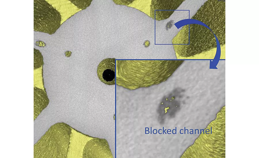
Blocked channels revealed without destroying the part. Source: Nikon Metrology
Interest in 3D printing is remaking the manufacturing landscape. Consulting firm IDC says global spending on 3D printers, both desktop and industrial, hit about $11 billion in 2015 and is forecast to reach $27 billion by 2019. Another research company (MarketsandMarkets) is saying 3D printing will experience 30% compound annual growth and reach $30 billion by 2022. In its April 2016 study, “3D Printing Comes of Age in U.S. Industrial Manufacturing,” Price Waterhouse Coopers (PWC) says compared to two years ago, more manufacturers (52% this year compared to 38% in 2014) expect 3D printing to be used in high-volume production in the next three to five years.
Metal-printed parts are being increasingly considered for lowering component weight without compromising on strength, for example in aerospace applications where decreased weight leads to increased efficiency. For such safety-critical aerospace components as well as automotive, energy, and medical devices, it is essential to know whether voids or inclusions are present, how large they are (both individually and in total), and where they occur—and also whether the dimensions of the part conform to those of the design.
In such cases, X-ray computed tomography (micro CT) is a powerful answer. By supplying a full 3D density map of the samples, micro CT gives all this information in an easy-to-read visual format.
You’d Inspect Welds, Right?
Using conventional manufacturing techniques, one would always inspect a weld for voids and inclusions. Well, in metal additive layer manufacturing, the whole sample is essentially one large weld! To not inspect it for voids, inclusions, and for dimensional accuracy would be a huge leap of faith in the technology.
Because of the chaotic nature of the 3D-printing process, with partially melted powder flying around in the printer, the position and nature of defects is often totally random.
With traditional manufacturing processes, a few radiographs at specific orientations can often give peace of mind. But with additive layer manufacturing (ALM), the whole part needs to be inspected. What do we look for when checking the structural integrity of ALM parts?
- Powder residues blocking channels
- Defects (voids and inclusions) – porosity, contamination, cracking
- Departure from the CAD model – dimensional analysis, wall thickness measurements, warping.
For example, a mold made using selective laser melting is designed to make a small knocker for a watch mechanism. Micro CT can determine the cooling and flow channels built in by the ALM process to an accuracy of 50-100 µm (depending on acquisition parameters). From flow/cooling simulations, this is known to be of sufficient accuracy for the purpose.
In fact, micro-CT can find defects within samples down to a resolution given by the number of pixels across the detector. Given a sample 100mm across, and a detector 2000 pixels across, the limiting resolution would be 50µm. Resolution is also limited by the focal spot size of the X-ray source, which may range from 80µm for high energies down to less than 1µm for low energies.
Defects below the nominal resolution may also be spotted if the contrast with the surrounding material is great enough. For example, given a 3µm X-ray focal spot, we can still see a 0.5µm gold foil edge-on.
The size of sample which can be scanned with CT depends on the material it is made of and the energy of the X-ray source (measured in kilovolts (kV)). Larger lower density samples can be scanned, as can smaller higher density samples.
Typical largest samples are:
- 225kV – aluminum piston heads; diesel injectors
- 450kV – aluminum cylinder heads; aircraft turbine blades
Maximum part size also tends to be limited by the size of the detector, but also by the penetrating power of the X-rays. This decreases as material density and atomic number of the material increases. Much more plastic can be penetrated than steel, and much more steel than lead.
To illustrate micro CT’s applications to ALM, here’s another example taken from one of the papers presented at the American Society for Precision Engineering (ASPE), which can be accessed here: https://www.researchgate.net/publication/283119260_ASSESSING_ADDITIVE_MANUFACTURING_PROCESSES_WITH_X-RAY_CT_METROLOGY.
In this research, a flexure mechanism fabricated by additive manufacturing is being investigated by X-ray CT scanning methods. A first flexure sample (AM1) was manufactured by fused deposition modeling (FDM), which for pedagogical reasons and with the aim of illustration will be called AM1. A second sample (AM2) was manufactured by stereolithography (STL). For reference, the FDM and STL processes have in general printing resolution of approximately 100 µm and 0.5 µm, respectively.
Micro CT scans show variance analysis for both AM1 and AM2 flexures against the original CAD model. From the measurements, it can be seen that deviations from the nominal geometry (CAD model) rise up to ±0.25 mm and larger when using the AM1 process. In contrast, the AM2 process generated part-to-CAD deviations mostly between ±0.1 mm, with a few exceptions particularly around surface edges or corners.
In addition to external checks, a cross section of AM1 shows residual internal and spatial deformations. On the other hand, the manufactured part generated by the AM2 process (bottom figure) does not reveal the presence of major deformations in the thin-walled flexure leaf structures.
Benefits
Micro CT is now much faster and more suitable for production-line use. Moreover, CT scanning of similar parts can be automated for loading and unloading. Scan times down to a few tens of seconds per part are possible. Users gain:
- Better insight into the inside of ALM parts
- Faster optimization of the ALM prototyping and production processes
- Quality control – much higher confidence in incoming and outgoing parts
- Reduced costs by avoiding destructive testing
With the rewriting of the manufacturing rulebook that 3D printing brings, X-ray computed tomography is a powerful partner for nondestructively assuring geometrical and tolerance quality control.
Looking for a reprint of this article?
From high-res PDFs to custom plaques, order your copy today!


