Automated Inspection of Critical Aerospace Components and Structures with Complex Geometries
As aerospace parts are becoming more and more complex, fabrication and materials automated inspections will become the only viable inspection method.
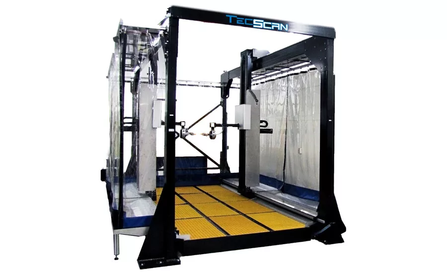
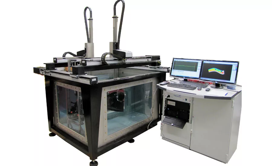
Ultrasonic squirter gantry system and immersion tank. Ultrasonic immersion tanks and squirter gantry systems are well suited for automated inspection of aerospace parts.
Ultrasonic squirter gantry system and immersion tank. Ultrasonic immersion tanks and squirter gantry systems are well suited for automated inspection of aerospace parts.
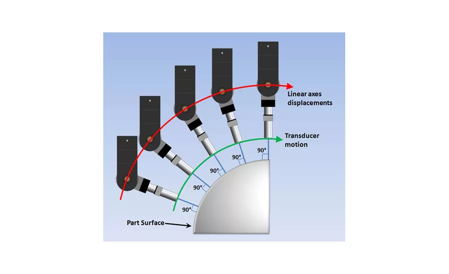
Contour following in the X-Z plane
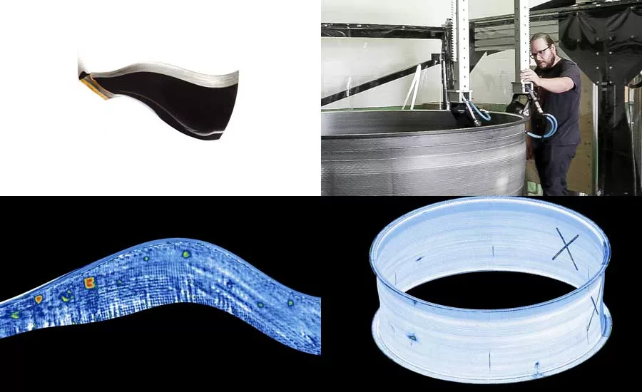
C-Scan image of sample engine fan blade. This example shows inspection result of aircraft engine composite fan blade and fan case. Automated ultrasonic testing and 3D contour following inspections were performed to detect defects. The first figure shows an example of a C-scan image obtained on a sample composite fan blade containing disbonds. These were created with Teflon inserts between the layers of the composite blade. The C-scan result represents a color-coded 3D presentation of the data collected during an automated inspection of the blade. The red spots on the C-scans represent the detected disbonds defects. Similarly, the adjacent figure displays a C-scan with defects obtained from a tested engine fan case sample.
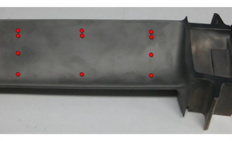
Thickness is measured at different positions on the blades by setting up gates on the front and backwall echoes. This example shows results of an automated point-by-point thickness control of sample turbine blade. The location of predetermined wall thickness measurements points on the blade were manually programmed to allow blades of the same model to be automatically measured.
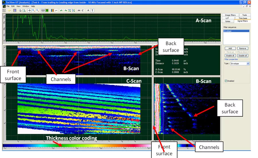
Superposition of the C-Scan image and a picture of the blade showing the approximate coverage of the C-Scan thickness mapping. The C-Scan result clearly shows all the cooling channels as well as their depth relative to the full thickness. The dark blue lines running from left to right of the C-Scan represent the holes in the blade. Variations in the depth of the holes and of the full thickness can also be observed by color variations in the thickness mapping. Such a representation allows measuring the thickness at any point of the C-Scan.
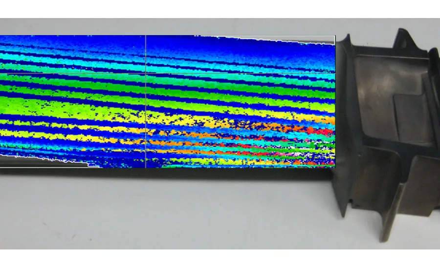
Superposition of the C-Scan image and a picture of the blade showing the approximate coverage of the C-Scan thickness mapping. The C-Scan result clearly shows all the cooling channels as well as their depth relative to the full thickness. The dark blue lines running from left to right of the C-Scan represent the holes in the blade. Variations in the depth of the holes and of the full thickness can also be observed by color variations in the thickness mapping. Such a representation allows measuring the thickness at any point of the C-Scan.
Aerospace components and structures come in all shapes and sizes and more importantly are made from different types of materials. These parts (components and structures) are also produced from different processes such as forging, casting, composite layups and even bonding of different materials. All of which require different verification methods. The only point in common is that they are all critical parts and need to be inspected to ensure quality and safety. Inspection of these parts varies greatly and can involve automated thickness measurements, bond quality detection for assembled components, porosity detection for parts made of composite materials, inclusion detection for forged parts, etc.
Automated Inspection Systems
With the use of automated ultrasonic testing systems, we are able to decrease the inspection time, increase imaging and detection capabilities as well as conduct reliable and repeatable inspections. Ultrasonic immersion tanks and squirter gantry systems are well suited for automated inspection of aerospace parts. Parts with complex shapes and geometries require immersion tanks and squirter systems with advanced scanning tools, such as contour following or 3D inspection software. These tools allow inspectors to set up inspection scan plans by teaching the part’s surfaces or importing a CAD drawing of the part.
Contour Following
Contour following can be described as the system’s ability to perform a controlled displacement of one or multiple axes, with the objective to move around a curved, round or inclined surface with constant transducer orientation and distance (water path). When performing an ultrasonic inspection with a large immersion or squirter system, the orientation of the transducer must be controlled with a high degree of precision in order to follow the parts contour adequately.
3D Inspection
Tridimensional inspection of parts with complex shapes uses computer-aided design (CAD) files to perform accurate inspection in 3D space. Sampling and interpolation are also performed in order to calculate a valid path trajectory for the scanner’s different axes.
An important step for contour following or 3D inspection is the validation of the scanner’s trajectories in the interpolated space. This verification can be done by comparing the deviation of the water path and probe incidence angle with a predetermined acceptable error.
While moving around the contour, a visual alarm can be set to advise the operator of deviations beyond this acceptable error. While water path deviations can be monitored from the time-of-flight of surface echoes, validating the incidence angle requires an indirect measurement. Setting a tolerance on the amplitude variations of the surface echo recorded at 0-degree incidence represents an efficient way of monitoring errors in the surface contour orientation; a large variation in the amplitude of the surface echo may indicate that the incidence angle at that location is not 0 degrees. If either alarm is triggered, a verification of the incidence angle can be done at the problematic locations and surface coordinates can be added or modified to increase the part definition accuracy.
After the part contour has been defined and validated, algorithms can be used to calculate the axes trajectories covering the complete part contour without any risk of collisions. Advanced ultrasonic software can map the selected part surfaces to the appropriate scanner axis and creates a 2D parametric space that defines the surface. The 2D surface can be defined in multiple ways from the defined surface contour (extrusion, angular revolution, rotational symmetry).
Automated Inspection Results of Aerospace Parts
Bond testing of composites parts
New generation fan blades and cases are designed for medium-haul airliners and constructed from composite materials. For safety and reliability requirements, automated ultrasonic testing is performed to detect any manufacturing anomalies/defects. The biggest challenge to inspect these parts is that they have complicated curvatures, surfaces with free form shapes, no axis of symmetry and varying thicknesses.
Wall thickness
Measurements of cast parts
Turbine blades used in aircraft engines are manufactured by investment casting. They are designed with internal air cooling channels which allow the blades to operate under extremely high temperatures. Thickness variation at the cooling channels, caused by the casting process, can affect the blade capacity to operate at elevated temperatures. Therefore, to ensure structural integrity of the turbine blades, it is important to control the material thickness at critical positions. Ultrasonic testing is typically done with the use of thickness measurement instruments with contact ultrasonic probes. This manual thickness measurement approach can be both time consuming and subject to human error. For proper and precise wall thickness measurement of multiple turbine blades, an automated inspection solution is highly desirable.
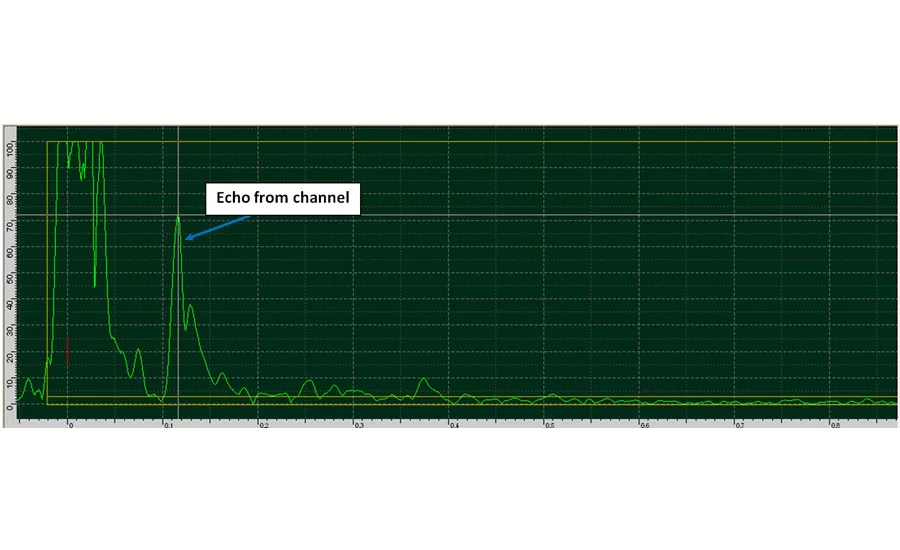
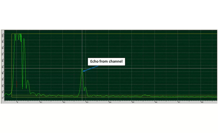
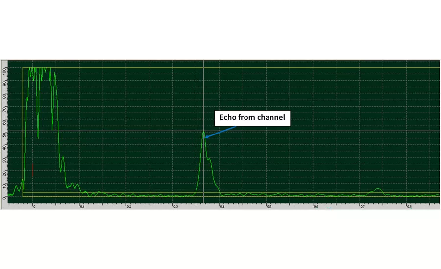
Wall thickness measurement of turbine blades can also be achieved from C-Scan thickness mapping. Using contour or surface following scans the full thickness mapping can be performed on large areas of the blades. The advantage of this approach is to eliminate uncertainties related to the blade’s channel positions as well as to detect any structural imperfections, including cracks and inclusions.
As aerospace parts are becoming more and more complex due to their shape, fabrication and materials automated inspections will become the only viable inspection method. These more challenging inspection criteria will pave the way for new and innovative automated solutions as well as inspection software that will enable operators to run inspections efficiently and, more importantly, more accurately.
Looking for a reprint of this article?
From high-res PDFs to custom plaques, order your copy today!


