Advanced Inline UT Testing

Multiple ultrasonic probes in Squirter configuration.
Inline automated manufacturing has quickly become more complex than ever. In order to ensure the quality of the product being manufactured, inline testing is now a critical part of the manufacturing process. Many different inspection techniques such as visual, electromagnetic, ultrasonic and many more are used in industry. Each method is intended for a specific purpose and has its own advantages and limitations.
Advanced inline ultrasonic testing allows manufacturing companies to monitor production parameters in real time, internal structure, bonding defects, the presence for foreign bodies and more. All of this information has to be acquired, processed and then displayed in a manner that a manufacturing company can take corrective measures or segregate the defective product. This interaction has to be done at very high speed and often the information has to be communicated to other machines such as PLCs, cutting or marking stations, conveyor systems and material handling manipulators in order for the corrective measures to be taken.
Ultrasonic instruments used for inline UT testing play a key role in successful and rapid inspection. These instruments have to be able to communicate with all kinds of machines, while collecting data and running automated flaw detection algorithms. In other words, we’ve come a long way from monitoring signals on analog ultrasonic instruments that sends the information to strip chart recorders for operator review.
Inline inspection systems description and requirements
Inline ultrasonic inspection can be achieved in different ways, but it starts with a properly adapted coupling of the ultrasonic probe(s) with the part. While immersion is usually viewed as an ideal coupling solution, it is not often a viable solution due to the manufacturing process, part geometry, high temperatures or other restrictions. Water jets or contact inspection with local water coupling often represent an interesting alternative. Depending on the inspection requirements, one or multiple probes may be used, either for faster coverage (multiple identical elements) or for required defects detectability (probes generating shear and compressional waves at different angles).
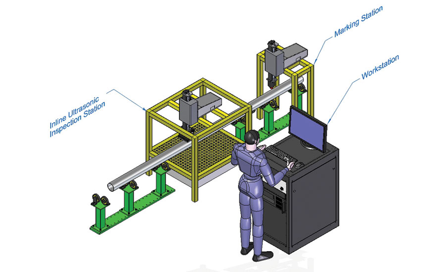
Representation of an inline inspection system with marking station.
Multiple ultrasonic probes in Squirter configuration
The probe(s) can be installed at a fixed position with the part being moved, or mounted on a scanning apparatus that move across a part on a fixed station. In either case, inspection must be performed at a high rate and preferably by monitoring probe or part position.
Adding inline UT testing capabilities to an industrial manufacturing process requires the automation of the testing system and its UT measurements and interpretation. Typically the UT testing capability is added between the manufacturing process and the quality correction process (for example, spray paint marking, cutting station, rejection chute, etc.). As a result, the inline UT testing system becomes the active bridge between the manufacturing and correction processes.
The inline UT system must therefore have the ability to receive information and commands from the industrial process, acquire and process ultrasonic data, and output the results in a format that can be used by the correction process. Such high level of processing is usually handled by the inline UT instrument of the testing system. These kind of advanced control and processing requirements cannot be met by commonly used UT flaw detectors.
An essential part of inline UT instrumentation is to possess programmable industrial inputs and outputs connections (I/O). It must have the ability to define input commands, or output information generated by the industrial process which needs to be interpreted by the UT instrument (for example, a command to start the acquisition). A somewhat open architecture of the UT instrumentation is desired in order to customize the inputs. The instrument needs also to allow defining custom sequences of operations based on the provided input. This represents a key element for integrating different industrial processes. The same applies to the outputs; sending relevant information to the industrial machine or to the correction process must be customizable. The output can take many forms, from an audible and/or light alarm to notify the operator of an anomaly, a signal that triggers the intervention process (open a chute, start/stop a conveyor, activate a cutting tool, etc.), a scaled signal that represents the ultrasonic data for display/review, up to a complete data file that contains the ultrasonic data as a function of positions that will later serve to cut the problematic sections of the part on a separate station. The ultrasonic unit must therefore be able to generate outputs in different forms, thus the need for programmable, industrial I/Os.
If corrective measures must be operated outside the production line (e.g. cutting station), ultrasonic data has to be associated with positions on the part. In such an example, the use of encoders that monitor part or probe(s) position is highly desirable for accurate positioning of anomalies detected by the ultrasonic unit on the part.
Another crucial aspect is the industrial environment into which the UT instrumentation may have to be installed. The apparatus must operate under the harshest electrical, mechanical and environmental conditions. It must therefore be built to sustain electrostatic discharges (ESD), electrical and electromagnetic noise, mechanical vibrations, as well as wet and dusty conditions. Signals have to be transmitted over long distances while being protected against outside noise, which is achieved by current transmission at high DC voltage levels (24V) and properly constructed shielded cables.
Ultrasonic instruments developed for such industrial applications therefore require state of the art ultrasonic hardware with high pulse repetition rates, fast data transfer rates, the integration and flexible I/O modules for both position monitoring and communications. All this hardware must then be controlled by a user friendly software that allows the operators to specifically tailor the ultrasonic output and configure the I/Os for their process and process control.
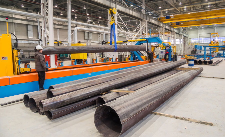
The wall thickness of pipes must be measured at different stages of production in order to ensure that the pipe specifications are met, or if any correction is necessary.
Ultrasonic UT instrument for inline testing
Some of these UT instruments are designed to operate with UT software in new and innovative ways. A well designed instrument will include ultrasonic measurement capabilities that can be used for thickness measurements, amplitude, attenuation, A, B, and C-Scan, Strip chart, etc. The user can choose to use among many analysis tools already implemented in the software platform or custom data processing algorithms executed within the software platform to export the required data in any known file format. These instruments must also have high-speed analog and digital inputs to communicate with a PLC or any other interfaces. Operators have to be able to configure the inputs/outputs according to the application; these can include alarm output, real-time measurements, stop/start acquisition, load a new inspection routine etc. In some cases these instrument and software combinations can be a great option for the upgrade of older or obsolete inline UT systems. In the end, the flexibility of the ultrasonic instrument is the key element to easy integration.
UT software application for inline control and data acquisition
Let's look at some examples of industrial applications.
Some of these industrial applications include wall thickness monitoring during production of pipes. The wall thickness of pipes must be measured at different stages of production in order to ensure that the pipe specifications are met, or if any correction is necessary. Implementing an automated UT solution requires that the UT device communicates with the manufacturing equipment and/or operators in order to identify and locate any variation of wall thickness. The entire process must be conducted at high throughput rates while monitoring the location of any variations from production specifications.
Another example of an industrial inline UT testing application is the monitoring of internal profile variations of manufactured products like tubes. Monitoring the internal profile ensures that the tube is manufactured within tolerance; the UT data can be transmitted, in the form of a wall thickness measurement file, to a cutting station where the tube can be cut at the appropriate locations.
Similarly, wrought billets are also inspected by inline systems, where internal or surface flaws such as voids or surface cracking originating from the cooling process are monitored. A scanning head in contact with the product or using water jets to generate the ultrasounds is either scanned across the billet or monitors the billet as it moves in front of the probes. Here, alarm outputs generated by the ultrasonic unit are associated with position along the billet and provided to a cutting station to remove the sections that don’t meet quality requirements.
Conclusions
With more demanding and complex manufacturing processes and faster production rates, quality control is a real concern for manufacturers. The integration of high performance inline UT inspection systems can help ensure that the quality of the products being manufactured will meet specifications.
Looking for a reprint of this article?
From high-res PDFs to custom plaques, order your copy today!


