Optics for High Accuracy Machine Vision
The best lens for a machine vision application is one that’s specifically selected for the sensor used in the camera.
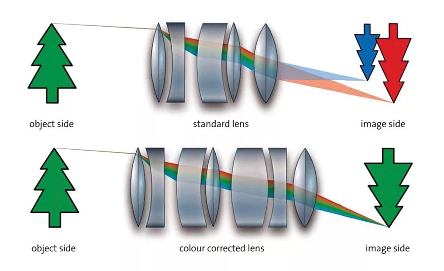
Figure 1. Correcting for chromatic aberration
High accuracy machine vision applications are dependent on the production of reproducible, high quality images, whether for inspection or measurement purposes. This means that the images must have sufficient resolution and proper definition of the areas of interest for the inspection or measurement to take place. Each element of a machine vision system has an important role to play in the overall outcome, but the optical system is a critical component since it forms the image of the object on the camera sensor. The construction of a lens system (lens radii, distances between lenses) as well as the distance between the lens and the sensor has an impact on the image.
Factors affecting lens performance
Once the field of view for the application has been determined, resolution and image quality are the most important selection criteria. Most lenses used in machine vision applications are fixed focus endocentric lenses which provide the same perspective as the human eye. In a perfect lens, all rays of light from a single point on an object plane will be focused to a single point on the image plane. However, all lenses suffer from imperfections that influence the resolution and quality of the image produced by the lens. These include:
- Physical defects. Surface defects will cause light rays to focus at a different point leading to blurring.
- Chromatic aberration. The angle of refraction of light through a lens is wavelength dependent, leading to color fringes on any images produced using white light with blurring on the edges of object’s image.
- Spherical aberration. Most lenses are spherical and a consequence of this is that the focal point for each ray passing through the lens is dependent on its distance from the center of the lens. The resulting images will show increasing amounts of blur towards the edges.
- Spatial distortion. All lenses suffer from a certain amount of distortion, in which the image is either stretched or compressed in a non-linear way, making accurate measurements difficult. In general, shorter focal length lenses experience more distortion than longer focal length lenses since the light hits the sensor from a bigger angle.
- Non-uniform illumination and shading across the image. With any lens, image brightness is reduced towards the edges and this is known as vignetting. Cos4 vignetting occurs because the light has to travel further to the edge of the image and reaches the sensor at a shallower angle. Mechanical vignetting occurs when the light beam is mechanically blocked, usually by the lens mount.
- Factors such as diffraction can also affect image quality. Diffraction results from the slight bending of light as it passes the edges of the entrance aperture to the lens. The smaller the aperture, the larger the percentage of light that is diffracted. Diffraction causes a point of light to spread out into a so-called ‘blur circle’ giving a reduction in the sharpness of the image. The overall optical quality of a lens is defined by the MTF (modulation transfer function) relating to the influence in detail contrast.
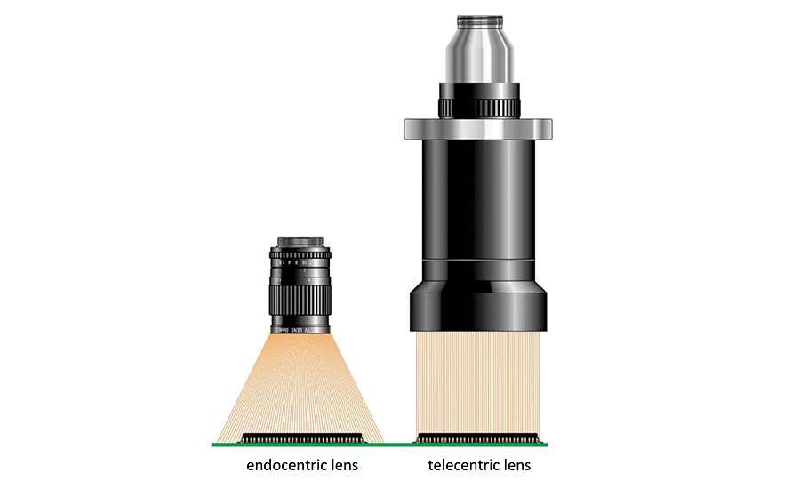
Figure 2. Light collection using an endocentric and telecentric lens
Making corrections
There are a number of ways to address the issues described above. Surface defects can be minimized by careful attention to the lens manufacturing and grinding process. Provided no color information is required, chromatic aberration can be avoided by using monochromatic illumination. This can be achieved by using a monochromatic LED source (often red, as it is the most economic) in conjunction with a matching filter to remove any extraneous wavelengths. Alternatively, white light can be used with a suitable bandpass filter. If color information is needed from the image, ‘color corrected’ lens assemblies are available where a number of lens elements are combined to compensate for wavelength dependent variations in refraction (Figure 1). Spherical aberration can be significantly reduced by using aspheric lenses that have been shaped to maintain the same focal point across the lens. Although there are software methods that can be used to correct spatial distortion, they cannot take the physical depth of the object into account, so it is better to correct by choosing the most suitable lens configuration. For short focal length lenses more complex lens designs are available to keep distortion low. If distortion is likely to affect measurements, it is better to use a longer focal length and increase the working distance, depending on the sensor size needed and the amount of headroom available.
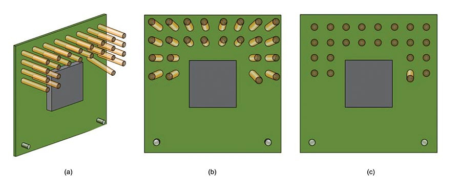
Figure 3. Use of telecentric imaging to eliminate perspective
Magnification, focus and perspective
The best lens for a machine vision application is one that’s specifically selected for the sensor used in the camera. The lens has to be able to illuminate the complete sensor area in order to avoid shading and vignetting. The lens also has to be able to resolve the pixel size of the camera sensor used. The magnification (or field of view) of a lens is defined as the ratio of the image size produced to the object size and is determined by the focal length of the lens and the working distance (distance of the object from the lens). As noted above, for the vast majority of industrial applications with a fixed object size and a fixed working distance, fixed focal length lenses are used. In order to resolve the details of the object and to ensure definite edge detection, the detail should be reproduced across about four pixels on the sensor, thus the required magnification is dependent on the required object resolution and the respective sensor pixel size.
For fixed focal length lenses, the adjustments available are generally only focus and/or aperture (iris) size. Reducing the aperture size can reduce some of the aberrations by preventing light travelling through the extremities of the lens and also increase the depth of field. Increasing depth of field means that the image will appear to be sharp and focused over a wider range of object distances. However, with a fixed focal length and a fixed lens position relative to the sensor, this range of distances produces perspective effects where objects of the same size have different magnifications depending on their distance from the lens. This can significantly compromise measurement accuracy. Aperture sizes are specified by F-number, but care must be taken since once an aperture is reduced below F8, the diffraction effects described earlier will limit the sharpness of the image.
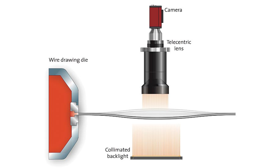
Figure 4. Drawn wire oscillating as it emerges from the die
Macro lenses
Macro lenses are specifically designed for small fields of view, which are approximately equal to the camera’s sensor size. Macro lenses are specified in terms of their magnification relative to the camera sensor and are optimized for ‘close-up’ focusing. Very good MTF characteristics and negligible distortion make them ideal for many vision applications. However, they lack flexibility because it is not possible to change the iris or working distance. Special ‘reverse rings’ can be used on some standard or high resolution lenses, allowing them to be used as a macro lens.
Telecentric imaging and illumination
Telecentric lenses are designed specifically for use in specialist measurement applications where perspective projections and incorrect image scaling can cause problems. They are particularly suited to imaging 3D objects where scaling can often be misinterpreted. Telecentric lenses collimate the light entering the lens across the whole field of view (Figure 2) meaning that all objects in the image have the same magnification irrespective of their distance from the lens, removing perspective distortion and making it easier to make measurements. Figure 3a shows an electrical assembly that needs to be inspected for damage. One of the pins is bent, and the imaging system needs to locate this fault. Figure 3b shows an image from a standard endocentric lens which shows perspective distortion, making it difficult to detect the problem. The pins appear to ‘fan out’ from the central axis of the lens. The bent pin appears very similar to the good pins and presents a much harder challenge to the vision software. Figure 3c shows an image of the same component produced using a telecentric lens. All the components except the bent pin now appear perpendicular to the lens, with no perspective distortion. The damaged pin is now revealed very clearly, making the job of recognition much easier. Another example involves accurate checking of the gauge of drawn wire as it leaves the die. Due to the nature of the process, a resonance often occurs in the wire which causes its position to fluctuate and this makes conventional lensing insufficiently accurate (Figure 4). As the distance from the wire to the lens is constantly changing, using a standard lens results in the apparent width or gauge of the wire also changing (Figure 5a and 5b). Using a telecentric lens however shows uniform magnification and focus on the wire irrespective of position (Figure 5c). As a consequence of collimating the light, the aperture of the lens needs to be the same size as the field of view, thus lenses with a large field of view are physically large (Figure 2) and can be very expensive. For the most demanding measurement applications it is also possible to get a double sided telecentric lens. This helps to maintain accurate measurements, even when the image starts to move out of focus, while increasing the depth of field further, and providing even lower distortion.
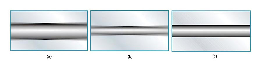
Figure 5. Use of telecentric imaging to provide uniform measurement and focus
Telecentric applications involving the measurement and inspection of flat surfaces and their defects place greater demands on the illumination system. For such applications, which include recognition of silicon wafer patterns and inspection of LCD displays, polished metal surfaces, plastic and glass panels among others, telecentric lenses are available with integrated coaxial light sources to homogeneously illuminate uneven surfaces and detect small surface defects such as scratches or grooves. An integral built-in LED source can provide excellent illumination stability and homogeneity with a reduction in the back-reflections often associated with conventional coaxial illumination systems. They are especially suitable for use when imaging highly reflective flat surfaces with reflectance greater than 30%. For applications where objects need to be back illuminated, such as high accuracy measurement of round or cylindrical parts, there are high-performance telecentric illuminators specifically designed for use with telecentric lenses. These offer higher edge contrast when compared to diffused back light illuminators and therefore allow higher measurement accuracy. It produces a distinct silhouette even when imaging transparent items.
Which lens is best?
With so many tradeoffs to consider when choosing the most appropriate lens for a machine vision system, understanding the application requirements and technology capabilities is essential. V&S
Looking for a reprint of this article?
From high-res PDFs to custom plaques, order your copy today!


 of a lens affects an image, as it is projected onto a sensor. Source: Stemmer Imaging")
