Industrial CT for Use in Additive Manufacturing Inspection
New part designs that would be impossible with traditional machining methods require new measurement tools.
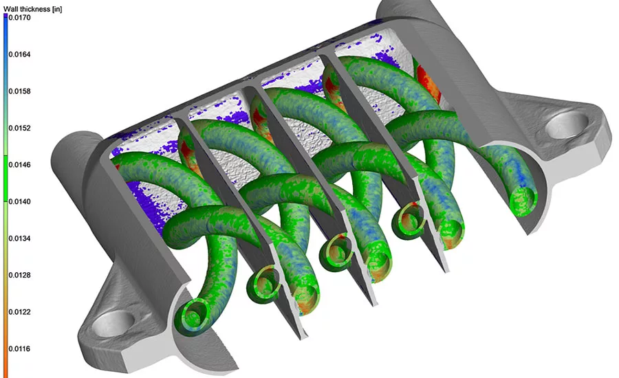
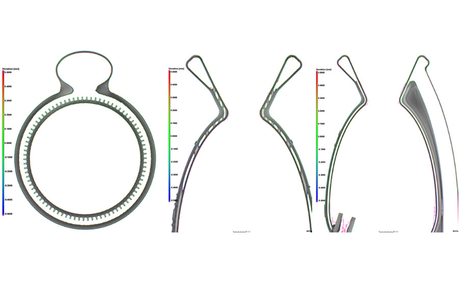
Wall thickness analysis of tubes designed to carry fluid and inspect channels for blockages. Source: Part by 3D Systems, Imaging by Delphi Precision Imaging
Every day additively manufactured (AM) parts are being used in new applications as the industry rapidly matures. As additive parts become more economical for small productions runs and move beyond use solely in tooling and prototyping, the need to nondestructively inspect parts for quality increases as well.
“Industrial CT is an excellent inspection method for additive parts and components from the automotive, medical implant and aerospace industries where quality and a high degree of reliability are critical,” says Blake Chenevert, president of Delphi Precision Imaging. Computed tomography (CT) has some advantages over other nondestructive inspection methods for additive manufacturing. With CT the entire 3D build volume of a part may be inspected and features uncovered within complex internal geometries.
Challenges Currently Facing The Additive Manufacturing Industry
Are there any defects in your additively manufactured part? CT is used for identifying un-fused powder, missed print layers or foreign object debris or other factors that may weaken the part and cause premature failure over the part’s lifetime, or cause contamination once the part is integrated into a final assembly.
Are your parts being produced as intended? CT scan results, combined with design data such as the CAD model, can reveal deviations internally on a point by point basis. Part-to-CAD, part-to-part and nominal-to-actual analysis measures multi-axis accuracy. Shrinkage and the dimensions and orientation of critical features within additive parts can be determined.
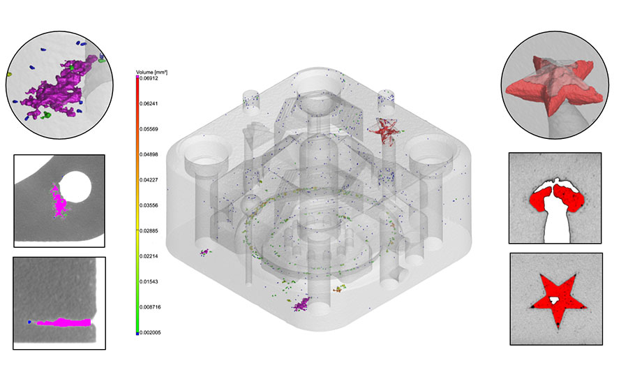
An industrial CT scan of an additively manufactured aluminum block with advanced analysis techniques. Purple represents porosity and a missed print layer. Red represents trapped un-fused powder within the star shaped feature. Source: Delphi Precision Imaging
Can industrial CT shrink your AM part product development time and increase production yields? Some complex metal parts have build times of anywhere from 24 hours to upwards of over a week to complete. It is inevitable that there will be a learning curve as new part types are developed. “Fail fast forward” is a commonly used term today among product development and hardware engineers building new products for the first time. While engineering is based on the hard laws of physics, there is a delicate dance of getting equipment to perform as expected and for new designs of parts to be printed as designed. Getting key data from the actual internal structures rather than just the as-designed models is imperative.
The costs and benefits of shrinking inspection and part qualification times. The nature of building a product up layer-by-layer allows the opportunity of introducing unique features within additive parts that don’t exist in subtractive or machined parts. The primary defects most commonly found in AM parts are un-fused powder within a solid structure, excess powder within an internal channel that is not fully removed or successfully cleaned at the completion of a part build, missing sections of a print layer (porosity), foreign material within a print build (FOD or high density inclusions) or an internal feature not adequately supported during the print process.
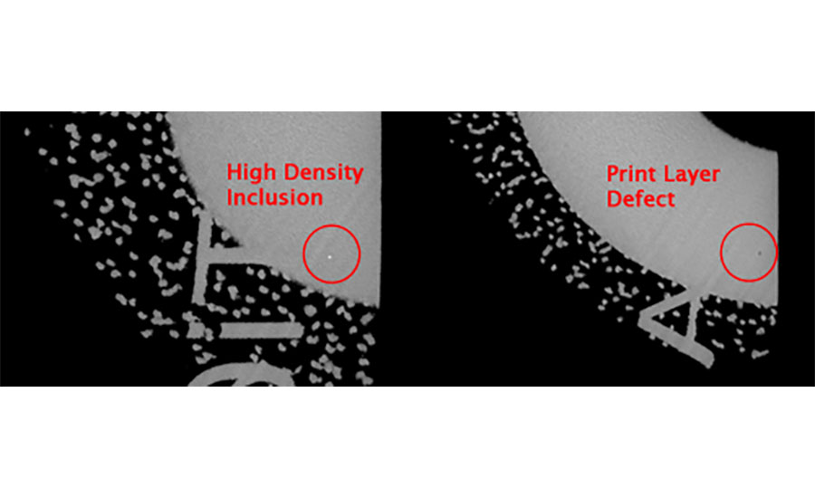
Print layer defects. Source: Delphi Precision Imaging
Quality Control Inspection for Additive Manufactured Parts
Measurement is key to maintaining quality control. New part designs that would be impossible with traditional machining methods require new measurement tools. “As quality requirements evolve inside of a disruptive industry like additive manufacturing, finding tools and innovative approaches to using those tools to advance nondestructive testing methodology is critical,” says Erin Stone, president of I3D MFG, a DLMS printer.
Visual Inspection of Internal Features
A simple but effective form of quality control is a quick visual inspection of a part for obvious defects. For parts with hidden interior features, this was not practical prior to CT scanning. CT data allows inspectors to slice the part in any X, Y, and Z planes at all critical locations. The X-ray penetration for each image is mapped to a grayscale histogram, which illuminates material/density differences similar to a standard X-ray image. If there is un-fused powder left in an interior feature, it will typically show as muted grey compared to the fused material, while high density inclusions will appear as a brighter white. If a print layer shift is visibly observed on the exterior of the part, a CT scan may show if there is internal porosity that could weaken the part. Conversely, CT scanning can also show that bonds are strong across particular layers, all powder is fused properly, and the part is viable for use in production.
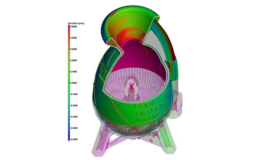
Rocker chamber. Source: Part by I3D MFG, Imaging by Delphi Precision Imaging
“The ability to see the internals of our as printed parts nondestructively at the microscopic level is a game changer. A micro CT scanner is a three-dimensional microscope which allows us to ensure the quality of parts. There is simply no other way to do this,” says Robert Swartz, chairman and founder of Impossible Objects.
For parts with critical interior channels such as heat exchangers, water cooled molds or fuel lines, a CT scan can reveal trapped powder, unwanted overhangs or blockages.
Porosity analysis after the completion of a CT scan quantifies the amount of porosity in a part or within a region of interest. Detailed porosity reports provide the percentage and volumes of porosities or inclusions in an entire part or a designated area of interest such as near thread tapping locations, inside of thin walls or at critical stress points.
Part-to-CAD and Internal Part Inspection
Measurement is key to maintaining quality control. New part designs that would be impossible with traditional machining methods also require new measurement tools. “CT scanning of DMLM metal parts has incredible benefits for our clients in aerospace and defense where quality is critical,” says Stone. “CT scan and analysis provides tangible and transmittable material data, helping DMLM build high quality standards inside of intensely requiring industries.”
Part-to-CAD analysis compares the dimensions of the printed part to the part as designed in the CAD file. Advanced analysis of CT data can provide detailed reports on total area within tolerance, and total porosity for the entire part of a critical area of interest. While laser scanning is usually faster and less expensive than industrial CT, it cannot see within the part.
“Creating unique geometries unattainable by conventional manufacturing is one of the main advantages of metal additive manufacturing,” explains Ryan Kircher, director, Metals Customer Innovation Center-Denver at 3D Systems. “Due to their complex design, many of these geometries can be difficult—or even impossible—to evaluate via conventional inspection methods like CMM or gaging. Even more advanced techniques like light and laser scanning have limitations. Advances in CT scanning capabilities make it a unique complementary technology for metal additive manufacturing. Industrial CT scanning allows for high resolution inspection of these geometries and features, while also providing information about the metallurgical integrity of the printed part.”
In addition to part-to-CAD analysis, CT data can be converted to mesh data (.stl) for part-to-part comparisons. “One of the most powerful uses of industrial CT that Delphi Precision Imaging has done was an analysis of a legacy flow valve. We compared a traditional, out of manufacture, cast and machined part, versus an additive manufactured replacement valve. The customer had conveyed that the flow rate on the new valve did not match the flow rate on the old valve. We preformed a scan of both parts, overlayed the .STL files of both parts, and it was instantly obvious that the CMM data used to create the original part missed a critical interior chamfer,” said Blake Chenevert. “That was a very happy customer.”
A cross section of a rocket chamber, cooling channels and propellant paths a seen from the X, Y and Z planes. Source: Part by I3D MFG, Imaging by Delphi Precision Imaging
Digital Radiography and Industrial CT Industry Standards
“Currently there are established standards that are being utilized industry wide for digital radiography or 2D imaging,” says Anthony Talberg, the lead technical sales and level 2 radiographer at Delphi Precision Imaging. “Most of these standards were adopted from similar principles in film radiography. More specifically ASTM 2737, which is intended to be a system longevity check, to ensure the major imaging components are performing as expected. ASTM 2597 is used to identify and correct defective pixels in the detector array.”
There are no current CT standards that are recognized industry wide, like the ASTM standards for radiography. Commonly what is being seen is that certain customers are generating their own internal standards.
Talberg says, “The problem with not having an established, industry standard is that each customer has its own specific set of criteria which makes the results in testing inconsistent. We have been adamantly working on developing our own internal process that will meet and exceed customer requirements, which we have proven out with multiple customers with some of the most stringent of requirements.”
Looking for a reprint of this article?
From high-res PDFs to custom plaques, order your copy today!


