Achieving Consistency and Reliability in Additive Manufacturing
How to create and maintain a quality assurance process.
Ensure your input material meets the machine’s requirements and has the characteristics required for AM.
Additive manufacturing (AM) has evolved from a platform of simple prototypes to the production of mission-critical components for use in high-tech industries such as automotive, aerospace and healthcare.
But challenges with achieving a uniform product have delayed the implementation of additive manufacturing by other traditional manufacturing industries.
The need for reliable, consistent parts is just as critical today as it was in the early stages of the industrial revolution. Original equipment manufacturers (OEM) want to know with a high degree of certainty that when they manufacture a part—same design, same material and same machine model—at multiple places or multiple times, they will get the same finished properties.
For AM, reliability is dependent on one’s machine, material and a robust or well-weathered procedure to carry out the process. With careful consideration, one can achieve consistency and quality with additive manufacturing time and time again. This article outlines the essential steps that must be implemented pre-production and post-processing for a laser-based, metal powder-bed fusion process to help ensure that products/components reliably meet specifications.
Pre-Production Considerations
With more than 150 variables possible during the laser melting process, it is important to examine the possible variabilities and account for the ones that are easiest to control. Sources of variation include, but are not limited to, the optics of the machine; the material placed in the machine; placement and orientation of the part;
and the build environment.
The following are some of the considerations you should have at different stages of setting up the process. As a best practice, maintain a checklist to capture potential issues.
Input Material
The input material (metal powder) has a significant impact on the success of the build, as well as on the quality of the printed part. The machine operator needs to ensure that the input material that will be used meets the requirements for the AM process—particle size distribution, density, chemical composition, and flowability.
The component manufacturers usually procure the metal powder from the machine OEMs to maintain warranty conditions. However, powder may also be obtained from a third-party supplier to help offset costs. If you prefer to go with a third-party powder supplier, make sure the machine warranty will not be declared void in the event of an operating incident. Consult with and secure approval from the machine manufacturer prior to using any third-party material. They will help you determine if the powder meets the machine’s requirements and has the characteristics required for AM.
Once you receive the material, review and document the details such as alloy designation, material vendor, the Certificate of Conformance/Analysis or associated test reports.
Maintaining a checklist of your processes will help you achieve process uniformity.
Storage and Handling of Powder
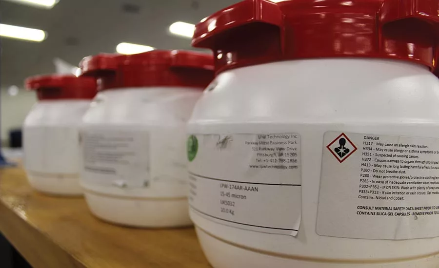
The metal powder needs to be handled and stored properly once it is received from the vendor. Proper handling includes documentation of the powder batch number or the lot number, storing the powder in humidity-controlled conditions and keeping the powder in its original canisters.
You should also record the date when the canisters are opened. Accurate record keeping is crucial during all stages of the process as it will help ensure material traceability. The powder should be handled in a clean and moisture-free environment to avoid contamination and the accidental pickup of oxygen and hydrogen.
Follow all safety requirements while handling the powder as it not only may cause injury to the handler but it could also create a condition which could trigger an explosion due to particle cloud formation by ultra-fine particles.
The Safety Data Sheet (SDS), a document that provides detailed safety handling requirements for every powder material, is an essential point of reference for anyone working with potential hazards.
Input Material Characterization
Refer to the material data sheet supplied by the vendor as it provides the details of the characteristics of the powder supplied. Features include the minimum required attributes of the raw material.
However, the details provided by the vendor may not be comprehensive so you will have to perform the powder characterization and document the results before the use of the powder in the machine.
Characterization of the input material will help you identify the material’s chemical and physical properties which can then be compared with the fabricated part’s properties. Incorporating this action into your process allows
you to evaluate the influence of any process characteristics.
Characterization includes a chemical analysis, determining the powder particle size distribution, powder morphology, density analysis and
flow characteristics.
Additionally, stock material will need to be strained with a sieve to remove any agglomerates or impurities. Make sure the sieve mesh is corrected to the material’s particle size to ensure proper sifting of the material.
Qualify Machine for Printing
Installation qualification ensures that the process equipment is compliant with the appropriate codes and approved parts design intentions. To qualify your machine, you need to make sure the machine not only functions as it was intended to by the manufacturer but also that the machine’s build environment is properly prepared for production as discussed below.
Machine Preparation
Starting with a clean machine is very important as leftover residue can stick to the machine, possibly contaminating the process and affecting subsequent builds.
Additionally, the presence of moisture in a machine can adversely affect the tensile strength of a product. Ensuring the machine is clean and dry is essential to the quality of the final printed part.
Select Build Plate
Select the right thickness for the build plate with the required thickness to avoid issues of warping. You will also need to examine the build plate for any warping or deformity from the previous build. Ask yourself if the build plate is smooth. If yes, you are ready for the next step which is to install the build plate over the build platform. Finally, you will need to document the dimensions of the build plate and its surface condition.
Utility Supply
Check to ensure you have enough gas to complete the operation process. Running out of gas in the middle of a build will adversely affect the final part.
Next, check for the proper flow of inert gas within the build chamber by properly setting the pressure gauge, the proper build plate temperature and the build chamber ambient temperature.
Final Inspections
Examine the recoater. If the recoater blade is damaged, the powder will spread irregularly in a non-uniform manner.
Spread the powder to check that it is spreading homogeneously on the table. This exercise will have to be repeated for several layers to make sure it is covering correctly.
Next, inspect the oxygen sensor to determine if it’s working correctly, then examine all other interfaces between your machine and your control software.
Finally, check the powder bin to ensure you have enough powder to complete the run. If you do not, the machine will stop abruptly and may not give you a consistent part.
In addition to the above, make sure that equipment maintenance record, calibration record, and preventive maintenance schedule are maintained for ready reference.
Best Practice
By following a procedure you can identify the risk that could arise at each stage of the process. Document the risk and develop corresponding mitigation plans. The knowledge of how the variability at different processing steps affect the part quality
is critical to refine your process
and ensure quality at every step
in the process.
Post-Processing Considerations
With post-processing, there are two significant actions to perform at this stage: retrieval of used powder and removal of the processed part, heat treatment and finishing operations.
Powder Retrieval
Depending upon the critical nature of the final application you might be able to reuse leftover powder in future AM runs. In order to avoid confusion on the condition of the powder during the processing stages, categorize the powder conditions into four groups:
- Virgin powder: actual raw material you receive from the vendor
- Used powder from build chamber: the powder that just came out of the machine immediately after finishing the print
- Sieved powder: the powder that is taken out from the build chamber and sieved to remove any agglomerates or impurities
- Blended powder: a mix of virgin powder with the sieved powder
There are many opportunities for a mixup if you are not maintaining or storing the powder properly with proper labeling or proper bins.
If any of the powder gets mixed up, your entire process will be a mess because typically one cannot recognize between used, sieved, virgin or blended powder.
Additionally, storing all four categories of powder separately and properly labeled helps protect from contamination or accidental mixup in the future.
Heat Treatment
Before removing the part from the build plate, you must perform a stress relief heat treatment. Failure to complete this will result in a deformed part. The key is heat treat, then remove.
Use an electrical discharge machining (EDM) or metal sawing operation to remove the part from the build plate, followed with the removal of support material from the part using hand tools.
Once you remove the part the real post-processing starts as the printed part may not have the required properties. You can achieve the required properties by doing another heat treatment based on the intended application.
The heat treatment (HT) cycle, which is specific to each metal alloy, is highly dependent upon the operation conditions where the part is going to be used. For example, the HT requirement is different for a titanium alloy when applied to aerospace or medical applications.
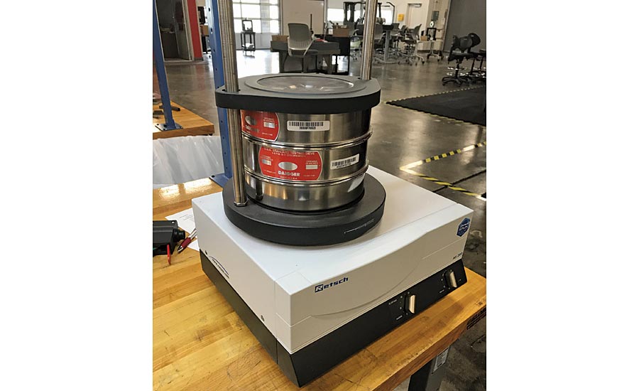
Sieving will remove any agglomerates or impurities from your material.
Best Practice
A heat treatment procedure needs to be in place which clearly explains the heat treatment (HT) cycle to be followed. The correct HT cycle is specific to each metal alloy and highly dependent on the operational conditions in which the component is going to be used. It is essential to follow the specified HT cycle to help ensure the quality and reliability of the final components.
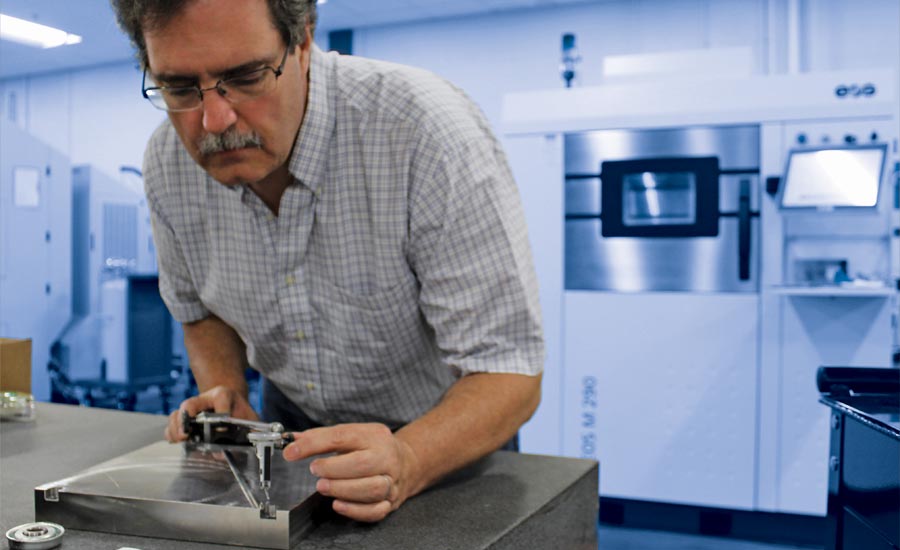
Dimensional Tolerance
The next step is to determine if the part you printed has dimensions within the tolerance limits. With this step, you compare the printed part dimensions with the actual design. Are they in agreement?
Next, check the surface finish of the part by performing a surface finish measurement and documenting the results. Be sure to check the surface finish from the top, on the vertical and the curved surface as the finish in all these regions will be different.
Finishing
Finishing operations such as machining, grinding, polishing, etc., may be performed to obtain the required surface finish.
Document all the post processing steps and make a note if the post processing affected the final part in any manner.
Final Part Acceptance
Once the part is complete, it will need to be tested to determine it has the right properties.
Acceptance activities can be performed by both destructive and nondestructive methods. Destructive methods include tensile, hardness, impact, compression, fatigue and metallography tests while nondestructive methods consist of computer tomography (CT), ultrasound, radiography, penetrant testing and eddy current.
Best Practice
Frame up an acceptance criteria before performing tests on the samples printed out during the qualification process.
Make sure the tests are performed according to established standards and the data is recorded in specified format. Nondestructive examination (NDE) techniques can be used for verification of the final geometry and for evaluating defects in the parts. Keep an accurate record of the data as it will be the basis for actual part production.
Getting to uniformity means maintaining the process at all times. Referring to the checklist will help you stay on task, resulting in the best production process possible.
Looking for a reprint of this article?
From high-res PDFs to custom plaques, order your copy today!


