Choosing the Right 3D Scanner
A quality engineer describes how he picks the right tool for the job.
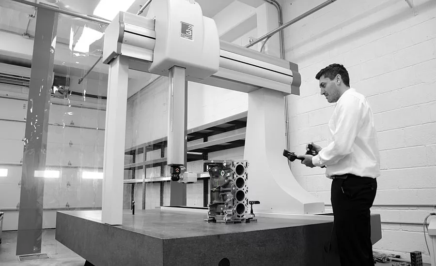
A CMM-controlled green laser line scanner measures a part. Source: Jesse Garant Metrology Center
To choose the right 3D surface measurement tool, an engineer must carefully consider the size of the object, the speed of the scan and analysis, and a customer’s tolerance requirements.
Nicolas de Cosson, quality engineer at Jesse Garant Metrology Center, recently described to Quality how he picks the right scanner for the job and the common applications for each of the metrology center’s scanning options.
White Structured Light
de Cosson opts for a handheld white structured light scanner for lower-resolution scans of objects that are larger than a cubic foot, yet smaller than unwieldy parts like a door panel. Like other structured light systems, the handheld device rapidly flashes a known pattern using white LEDs across the object’s surface; depth and surface information is calculated based on how the pattern deforms over the object’s surface and is stored as a point cloud. After post-processing, the model can be exported as an STL or another similar file type. The end result is a quick, relatively inexpensive scan. Garant has the Artec Eva, which features a scanning resolution up to 500 microns and a 3D point accuracy of 100 microns.
“Depending on the project requirements, higher resolutions and increased point accuracy may not be necessary,” de Cosson says. “Perhaps the project’s tolerances are greater than 500 microns. We’ll be able to perform the project’s requirements quickly and efficiently. Something else that we consider is the file size—and with the Eva, file sizes tend to be smaller.”
Common applications include reverse engineering and part-to-CAD comparisons. De Cosson recalls a recent example of a customer who received castings from China and Mexico. The castings from China were about five pounds heavier than those from Mexico, and the customer needed to find out why. “So they asked us to use the white light scanner to get an overall sense of the object’s geometry and to quickly point out what the differences were by doing a part-to-part overlay.”
Blue Structured Light
Garant has two different blue structured light scanners in the shop. For jobs requiring higher resolution than the Eva, de Cosson can use the Artec Spider structured blue light scanner. The trade-off is a slower and more expensive scan. “That could certainly be a limitation for some people,” he says. “But the scan is much, much higher resolution. The blue light scanner from Artec has a point accuracy up to about 50 microns and a resolution up to 100 microns. So, that’s definitely a big difference.”
Applications for the Spider are similar to the Eva, just for smaller components with tighter tolerances. “The field of view of the Spider is a lot smaller than the field of view of the Eva. So you’re also going to have size limitations.”
The other structured blue light scanner is a Rexcan DS3. “Its primary use in the field is for jewelry, but it can be used for all types of complex geometry. It is also highly accurate,” he says. “It has a resolution of about 17 microns, which is pretty crazy.”
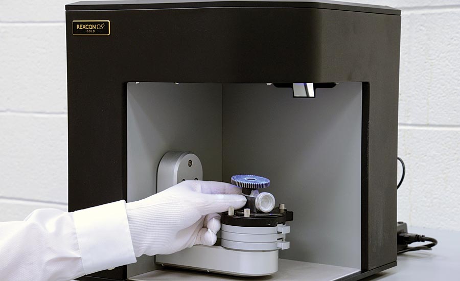
An engineer places a part into the Rexcan DS3 to be scanned. Source: Jesse Garant Metrology Center
The trade-off here is an even smaller scanning window.
“It’s more appropriate for very small objects, things that are perhaps 100 millimeters, maybe a little bit smaller,” he explains. “But we can push it a little bit.”
In contrast with the handheld Eva and Spider, the DS3 is automatic. “So in terms of throughput, it’s a really great system. You set up the objects on plates beforehand and allow them to run, and it will automatically go through a predefined path that captures the entire surface.”
Both the white structured light and blue structured light have limitations, particularly for scanning deep recesses or holes like those in an engine block. If the scanner can’t see it, then it won’t be able to capture it. Similar limitations exist with transparent or black objects, a challenge often combated by spraying the object down with a thin, white developer powder.
CMM Laser Line System
For much larger objects like door panels, de Cosson can choose a green laser line system attached to a large CMM. It uses a form of triangulation to bounce a laser line off the object’s surface, which it recaptures to create a point cloud. It has a point accuracy up to 40 microns.
The laser line scanner can be used in conjunction with the CMM’s touch probe. “Depending on the part’s geometry and if there are deep holes that cannot be accessed by the optical system, we can swap out the laser head for a touch probe. In this sense we are able to get the best of both worlds—a highly accurate and repeatable touch probe system and the speed of a light-based system. However, this is one of its major limitations, if the laser cannot see the feature to be measured then we cannot use the system.
“Across the board for all of the optic systems that we have, a lack of visual accessibility is primarily why we lean heavily on computed tomography. With the optic systems, there are just certain features that are not able to be captured. So, for the green laser, it’s much more about creating a surface profile on larger flat objects like door panels—features that don’t have deep cavities or holes that would require measuring.”
Like with the handheld structured light scanners, common applications for the green laser include part-to-CAD, part-to-part and GD&T.
Practicality determines whether de Cosson chooses the green laser over projected light options.
“We have a large CMM table, and so if we have large objects and we need to hold that point accuracy over a greater distance, then we’ll use the CMM,” he says. “For example, you wouldn’t use the Spider if you were trying to scan highly detailed objects over large spans. You’re going to lose your point accuracy over larger distances. But if you’re scanning something on the laser system, it will hold its point accuracy over the entire span of the table. Our CMM table is just over eight feet long, and as such the size and high repeatability are major reasons for choosing to use the system.
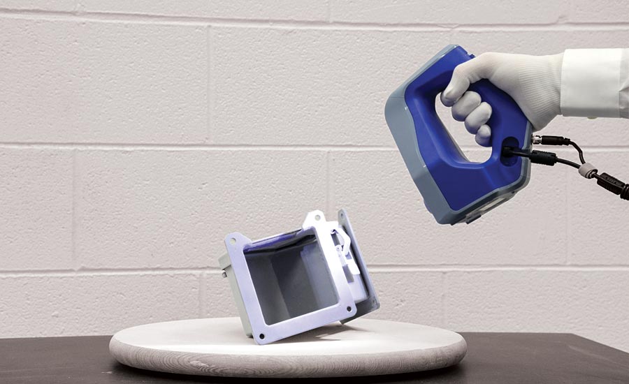
An engineer uses the Artec Spider to scan a part. Source: Jesse Garant Metrology Center
“Yet, for it being that accurate, you pay for it in the size of data. Your point clouds are massive, it’s a long processing time.”
Conversely, the handheld projected light scanners offer advantages of mobility and flexibility.
“You can be quite nimble as you’re moving around the object and trying to capture all these different details,” he says. “Whereas on the laser system, each time that you have to get a different angle, you have to move the head away from the object. Then you have to rotate the head to a specific angle and move it back into place. So it’s not nearly as efficient.
“Where the CMM laser line shines is the ability to record all of the movements into a program that can be recalled multiple times. Then using fixtures on the table, you can take the object off the table and put the next object on and run the program again. So you spend a lot of time programming upfront, but then you save time in the long run.”
For any of the four options, practical concerns of micron resolution, speed, and data size are taken into consideration.
“Certainly, it’s going to be much faster to use the Eva, Spider or even the Rexcan with respect to one-off projects with complex geometry. You get a visual feedback of the point cloud that’s coming up on the computer screen. This way you can see directly what you’re scanning. In a sense the same is true for the line laser, but it’s not quite as detailed and is not represented in color. In fact with the laser the texture is not being captured at all, all you get is surface detail, so in some cases this will also swing our choice on what system to use. All in all there are many factors that come into play when choosing the right system, yet what really matters is how best to serve the project at hand and to get the best quality deliverable to the customer.” Q
Looking for a reprint of this article?
From high-res PDFs to custom plaques, order your copy today!


