The Noise in the Background
Ensuring accuracy with helium leak testing.
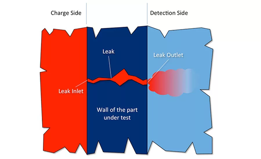
Figure 1. A close-up view of a leak
From airbags to air-conditioning units and fuel rails, from anything implanted in the body to hermetically sealed enclosures for integrated circuits, there are some instances where the acceptable leak rate is so small as to be practically zero. Few air leak test methods, such as pressure decay, have the necessary detection range.
These situations call for a trace gas-based test method.
Why?
Most air leak test methods measure leaks indirectly, through the change in a physical quantity (e.g. pressure change caused by a leak). This most sensitive detection range possible with this approach is approximately 1x10⁻³std.cm3/sec for very small parts.
Trace gas methods, on the other hand, measure leaks directly. The actual flow rate of trace gas that is exiting the leak is measured. This allows for a much more sensitive detection range. How sensitive? As little as 1x10⁻⁹std.cm3/sec – roughly 1 millionth of the low limit of an air leak test.
Let’s have a closer look at a leak exposed to trace gas (see Figure 1).
One side of the leak (charge side) is pressurized with a trace gas while the concentration of the same gas will be measured on the other side (detection side).
In many case, the charge side is the inside of a part, but there are some cases (especially when checking hermeticity) when the outside of the part is charged.
Both sides have their own challenges.
Charge Side
It is very important to ensure the highest possible concentration of trace gas at the inlet of the leak as the gas exiting the leak will have the same trace gas content.
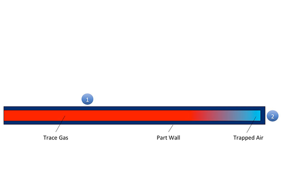
Figure 2. Long linear parts without part evacuation. A leak in Area 1 it will be easily detected as the gas exiting the leak will have a high concentration of trace gas. A leak in Area 2 has a very poor chance of being detected because the gas analyzer will only detect a concentration of leaking trace gas. Trapped air escaping through a leak will not be detected. The time it takes for this trapped air to escape from the part in Area 2 and allow trace gas to pass through the leak at a measurable level may exceed the cycle time of the test—the leak will slip by undetected for a false pass of the part.
The solution is evacuating the part before testing to as high a vacuum level as possible. When this is not an option (e.g. due to the possibility of the part collapsing) and if the part has multiple inlets and outlets, allowing trace gas to flow through the part is also an option.
Detection Side
In direct contrast with the charge side, here we want to achieve as low a concentration of trace gas as possible before the test begins.
Why? Because leak detectors can’t differentiate between the trace gas exiting a leak and the concentration of the trace gas that is already present in the atmosphere. This atmospheric concentration of the trace gas is referred to as background.
Background can be suppressed/eliminated either by
- using signal processing, or
- physically, though various techniques.
Signal processing attempts to mathematically compensate for background levels. But this still leaves a wide margin for error that can lead to unreliable test results.
Physical reduction of background can substantially reduce the risk of error. This can be accomplished by lowering either the pressure surrounding the test part or replacing the contaminated atmosphere around it with trace-gas free inert gas.
Let’s take a closer look at the available means of background reduction for the most common test methods, beginning with the hard vacuum method.
Hard Vacuum
This method, which most often uses helium as the trace gas, allows for the detection of the lowest leak rates.
The detection side in these systems is typically at less than 1Torr (mmHg) pressure. A vacuum chamber is used to achieve such a low pressure.
Every square centimeter of the interior surface of the chamber outgasses during chamber evacuation and test. At the end of test, the chamber is under vacuum and needs to be brought back to atmospheric pressure. Whatever gas is present during the venting of the chamber will be the one outgassing in the subsequent test.
If the helium concentration in the chamber was near atmospheric, then the gas adsorbed on the walls will be reasonably helium-free air. If, however, the last test ended in a large release of helium (due to a leak), then the gas adsorbed will be helium rich. In that case, the background helium level will be much higher than normal during the next few tests. This will skew test accuracy.
Sound chamber design practices, such as minimizing surface area, eliminating trapped volumes and reducing complexity in general, are crucial to avoid such trace gas build-up problems.
When testing for ultra-low leak rates, signal processing is commonly used. “Zeroing” (see the Atmospheric Methods section) is one of these techniques. It is used together with various novel technologies to eliminate the effects that hydrogen in the chamber can have on helium readings (i.e. false high readings).
The Shortcomings of Atmospheric Methods
Atmospheric methods have gained market share due to their lower cost and complexity in the past decade. Improvements in background suppression/elimination techniques have made these methods feasible alternatives where hard vacuum testing was once the only reliable option.
Using signal processing (zeroing) to minimize the effect of the background is very common. Almost all leak detectors on the market today are equipped with this function. The leak detector simply takes a snapshot of the leak rate when the function is activated and subtracts this tare value from all subsequent measurements. The tare value is adjusted lower should the leak rate attempt to turn negative (i.e. if the measured leak rate gets below the level measured when the leak detector was zeroed).
This a very useful feature when trying to find small leaks in a trace-gas rich environment. It does, however, come with a few caveats.
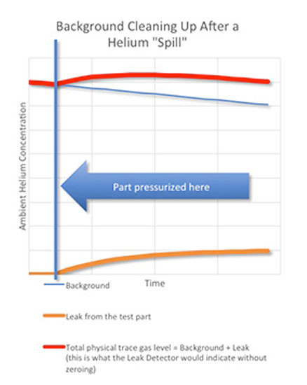
The graph above shows the physical helium levels in the test area during a test in a helium-contaminated environment.
The background level is slowly dropping as the extra helium dissipates (blue curve).
Let’s assume there is a leak that appears when the part is pressurized (brown curve).
The total helium concentration that the leak detector measures will be the sum of the background and the leak-induced concentrations (red line – note the dropping characteristic).
In most scenarios, the leak detector is zeroed when the part is pressurized.
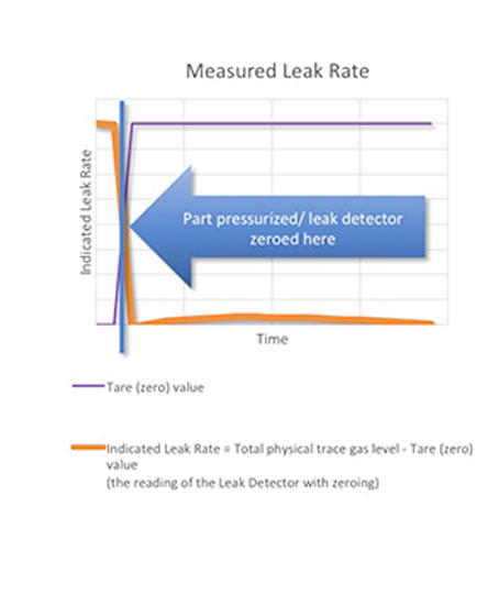
The graph above shows the leak rate indicated by the leak detector after zeroing:
When the zeroing function is activated, the leak detector stores the leak rate as the tare value and begins to subtract it from the readings. If the background was steady, the proper leak rate would be indicated. But because the background level is dropping AND the measured leak rate (the sum of the helium level from the leak and the background level) never got below the level measured when the leak detector was zeroed, the leak detector will show a dropping leak rate, eventually no leak at all!
Due to the potential difficulties described above, many manufacturers and quality engineers prefer physical background reduction techniques. These vary by test method:
Sniffing
A sniffer leak detector consists of a sniffer probe which samples the surrounding air with some form of analyzer (a mass spectrometer or other sensor).
Gas management (i.e. the removal of trace gas and adequate ventilation of the test area) is vital when setting up a sniffer-based test station. It is the only means of physically controlling the background.
Accumulation
Just like in sniffing, gas management is very important. This method is somewhat less susceptible to background fluctuations as it measures the increase in helium concentration, not the absolute value. But a very high level of background can still have a detrimental effect in measurement accuracy.
Proper sealing of the accumulation volume and the related circuits makes the test more robust. In some cases, replacing the atmosphere inside the system with nitrogen is also an option.
Nitrogen Purge Technology with Leak Test
This method uses an inert gas (usually nitrogen) to “carry” the leak signal from an isolated test area into a leak detector probe that samples the trace gas concentration. Because the inert gas replaces the atmosphere inside the chamber, background trace gas levels are minimized.
Instead of using seals to isolate the test area from the outside world, another technology uses a gas seal created by a very small flow of nitrogen around the perimeter.
This approach creates a test zone around the entire part, or a particular area of interest (e.g. joints, ports, etc.). Complex assemblies like HVAC systems or engines are built up of components that have already been tested. The connections of these parts, however, have not.
This method allows testing for leaks at a level that is comparable to a mid-range hard vacuum system without the need to create a vacuum around the test area.
Conclusion
All trace gas-based test methods depend heavily on sound gas management practices. Paying attention to these details when designing a test system can save many headaches during the commissioning of the system and in production.
Looking for a reprint of this article?
From high-res PDFs to custom plaques, order your copy today!


