Seeing is Believing: 2D and 3D X-ray Technologies for Nondestructive Testing
X-ray based techniques have many advantages for inspection and quality control.
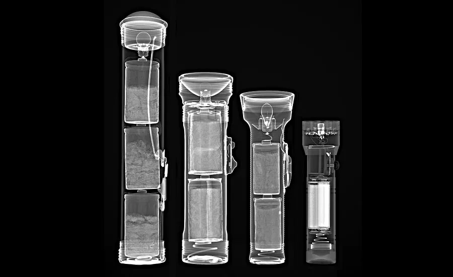
X-ray image depicting the evolution of flashlights (from left to right: 1900s fisheye flashlight; 1930s solid copper flashlight; 1960s ribbed chrome flashlight; modern LED flashlight with a laser pointer). Source: Nikon Metrology
Two-dimensional and 3D X-ray technologies are among the most useful nondestructive testing methods. They enable the inspection of an object’s internal features without having to disassemble the sample or destroy the part in the process. Several X-ray based technologies began in medicine and then found use in industrial applications. Today, X-ray technologies are increasingly being used in the quality control industry for nondestructive analysis and 3D imaging in industries such as aerospace, automotive, electronics, medical devices, plastic components, and 3D printing (additive manufacturing). Some of the X-ray based techniques that can be used for NDT include radiography, laminography, computed tomography, limited angle tomography, and computed laminography; they can be of assistance with the determination of voids/porosity, flaws, cracks, inclusions, and the performance of geometric dimensioning and tolerancing of manufactured parts. Recently, there has been an increase of surveys in the field of X-ray based technologies for NDT. According to a recent report produced by Research and Markets, the global market for industrial X-ray inspection technologies (X-ray computed tomography, radiography, and film-based systems) is estimated to exceed $722.4 million by 2024.
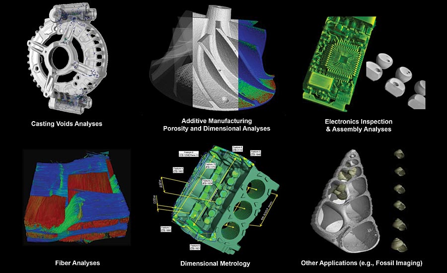
X-ray based technologies are used for inspection across various applications and industries. Source: Nikon Metrology
2D X-ray Imaging Techniques
The first and still widely used X-ray based technique is radiography, which aims to produce an image projection of the internal structures of an object onto a detection screen. Applications of industrial radiography include the inspections of welds and electronic components. Different degrees of packages—from light-emitting diodes, hybrids, power devices, multi-layer wire-bonded packages to ultra-fine pitch devices—can be inspected for package requirements or defective behaviors. By taking 2D radiographs at multiple angles, the depth of features and layers of an electronic assembly can be discerned. Typical inspections take place on fully populated printed circuit boards (PCBs) to examine the condition of the package’s voids, concentration area, solder bridges, pad alignments, etc., and to look for traces of failure such as wire sweeps, shorts, excess/lack of solder in the joints, cracking, undersized or oversized elements, and missing components. With high magnification, form and voids in ball grid arrays (BGAs) can be clearly visualized and quantified with modern analysis software, and by using a pass/fail threshold condition, an analysis of tolerance can be provided. By angling the detector away from the sample and rotating the sample while taking multiple radiographs, it is possible to build a 3D model of a part with what is called ‘laminography,’ also referred to as “motion tomography.” Going one step further, X-ray computed tomography (CT) is a 3D measurement technique that enables the creation of a 3D model for the entire volume of a scanned object in a nondestructive fashion.
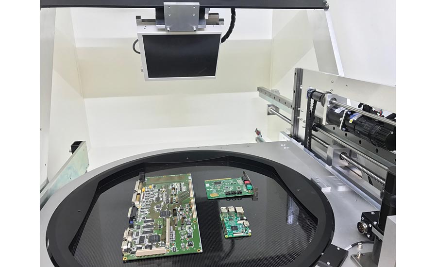
X-ray inspection of electronic circuit boards. Source: Nikon Metrology
3D X-ray Imaging Techniques
The CT technique allows the visualization and analysis of internal structures using cross-sectional images. It has the ability to generate geometric data for the characterization of material structures and the detection of cracks or flaws. X-ray CT machines for industrial applications are primarily equipped with an X-ray source tube and a detector, between which a workpiece specimen can be mounted on a rotary table that rotates while the detector records radiographic images at different angular positions. The X-ray beam emitted by the source passes through the specimen, in which the interactions of the X-ray photons with the workpiece material attenuate the intensity of the beam. Therefore, X-rays traversing different paths through the specimen will emerge with different intensity attenuations, which are subsequently measured by the detector.
After collecting several radiographic images taken from a large number of different angular positions around the specimen on a 360º rotation, with the aid of a reconstruction algorithm, it is possible to reconstruct a 3D image of the workpiece detailing all of its internal and external features. In X-ray CT, the 3D image resulting from a reconstruction algorithm represents a volumetric density map—visualized as grey levels (although false colors can be added to different sections through a segmentation process)—of the mean X-ray absorption coefficients for the workpiece specimen along the crossing paths of the X-rays photons. This grey level map depends not only on the density and composition of the specimen’s material but also on the energy of the X-ray photons passing through. Each gray level contains information about material that the X-rays have penetrated along the entire line connecting the source and the respective detector element, thus revealing external and internal structures of an object. While the object’s surfaces are not explicitly defined by this technique, they can be extracted from the reconstructed volumetric gray level map using a surface determination algorithm. Once the surface determination is made, with appropriate calibrations, CT analysis can then provide dimensional measurements of the part.
The insight gained from imaging an object’s internal structure is quite valuable. The 3D reconstructed model contains all internal and external geometry, allowing for analysis through the use of clipping views or cross-sectional images with high spatial resolution. Being able to see inside a product allows for easy validation of parts, identification of design issues, investigation of discrepancies, location of flaws such as cracks and voids, and dimensional inspection. This information ensures that components are structurally and functionally sound, which can enable the prevention of failures. The 3D volume can be inspected slice by slice, compared with a computer-aided design (CAD) model, inspected for defect analysis, and measured for wall thickness analysis.
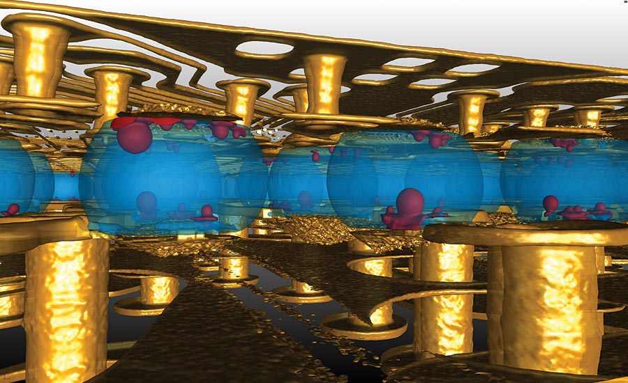
Layers in a PCB segmented by color to show the porosity of the BGA. Source: Nikon Metrology
Dimensional Metrology and Defect Analyses
In the field of dimensional metrology, CT can obtain dimensions of internal features normally inaccessible with coordinate measuring machines (CMMs). Thus, parts can be inspected not only for go/no-go, but also for accuracy of manufacturing with quantifiable measurements. As a result, interior measurements can be obtained as well as localization of structural material imperfections and identification of assembly errors not usually visible through traditional methods of nondestructive testing. Dimensional measurements with CT allow for size and form determination, wall thickness analysis, and part-to-model or part-to-part comparison against a standard (with color mapping). In addition, CT enables reverse engineering by converting the 3D reconstructed model of a part to a stereolithography CAD model, which can be used for 3D printing and computer-aided manufacturing.
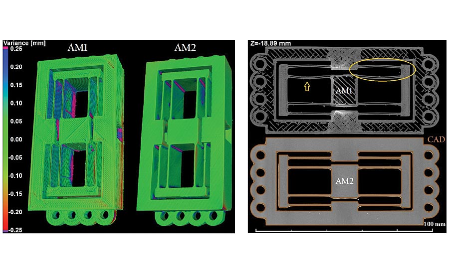
A part-to-CAD comparison for two identical flexures produced by two different AM processes (right) and transversal cross sections showing internal spatial deformation in the flexures (left). Source: University of North Carolina at Charlotte, NC
A Partner in the 3D Printing Revolution
Additive manufacturing (AM, or 3D printing) can produce highly complex geometries and customize parts directly from the part design model without dedicated tooling. However, many questions about the structural integrity of 3D printed parts—tolerance limits, layer defects, residual stress, and material inclusions—remain unanswered because AM process parameters and disruptions during the material layering (generally in powder form) may induce dimensional deviations and internal flaws (cracks or voids) in the final product. These flaws might affect the performance of AM devices, so NDT techniques are needed.
Since CT shows several advantages as a nondestructive method for acquiring structural characterization of both internal and external geometries of AM parts, it is often the only viable option to extract component dimensions of internal or hidden features. Thus X-ray CT is typically used to detect porosity and cracks in AM parts, dimensional deviations from CAD models, and powder residues or inclusions left inside the AM built part. Naturally, the capability of defect detection by X-ray CT depends very much on the part’s size, complexity, and material, but in principle, high scanning metrological resolutions in the order of 10 µm or less are possible.
Practical Considerations
Parts of varying size and complexity can be measured using X-ray based technologies. By changing the position of the specimen with respect to the source-detector distance, different magnifications can be achieved and the resolution of the scans can be modified. A high resolution close-up view of a specific region of interest can be obtained. Accurate measurements can be performed using high resolution scans, and faster acquisitions can be achieved with lower magnifications. If time is a constraint, a loss of image quality can be tolerated as a tradeoff for a reduction in scan time. A reduction in measurement time of several minutes may lead to a reduction in measurement accuracy of only a few micrometers. Reduction of scanning time down to 30 seconds is possible depending on the application. Semi–automated and fully–automated X-ray inspection processes are also possible, which allow for the use of 2D and 3D X-ray technologies on production floors. Ultimately, the quality of the CT data depends on the quality of the X-ray images, which is in part dependent upon the quality of the X-ray source, the signal-to-noise ratio in the detector, and the precision and stability of the manipulating system.
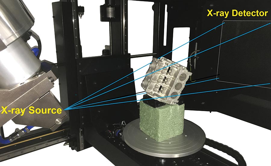
System showing an X-ray source tube, a detector, and a sample mounted on a rotary table before CT scanning. Source: Nikon Metrology
Conclusion
With its ability to improve product quality, reduce inspection and analysis costs, and decrease manufacturing time to market, 2D and 3D X-ray technologies are now being rapidly adopted in industries such as 3D printing, automotive, electronics, aerospace, medical devices, cast materials, and injection molding. X-ray based techniques have many advantages for quality control mainly because it allows for the extraction of internal features in a nondestructive fashion. Being able to see inside a product allows for easy validation of parts, identification of design issues, investigation of discrepancies, location of flaws and internal defects, and dimensional inspection. Today, X-ray based technologies are typically used for the inspection of a variety of components made of polymers/plastics, ceramics, casting and light metals (e.g., aluminum), fibers, composite materials, and several combinations of mechanical and electronic assemblies.
In addition, X-ray CT can be used as a quality control tool from optimization to production or to identify or prevent failures quickly, which saves both money and time.
Other References
H. Villarraga-Gómez, “Seeing is believing: X-ray computed tomography for quality control,” Quality Magazine, Vol. 55, no. 6, pp. 20-23, June 2016.
Looking for a reprint of this article?
From high-res PDFs to custom plaques, order your copy today!


