Reverse Engineering for a Model-Based World
The list of reverse engineering applications is long and will continue to grow as engineers create new and creative ways to use the technology.

The list of reverse engineering applications is long and will continue to grow as engineers create new and creative ways to use the technology.
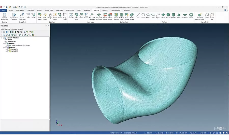
The part was measured with a laser scanner on a portable arm to capture the necessary point-cloud data that was then used to create a 3D mesh.

The open ends of the mesh are then exported to edge splines, which creates the first two curves that will define the surface. Next, the slice tool is used to create curves parallel to the ends and perpendicular to the flow axis.
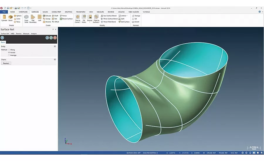
With the curve network complete, a Net Surface tool is used to create a NURBS surface, rather than a collection of patches.
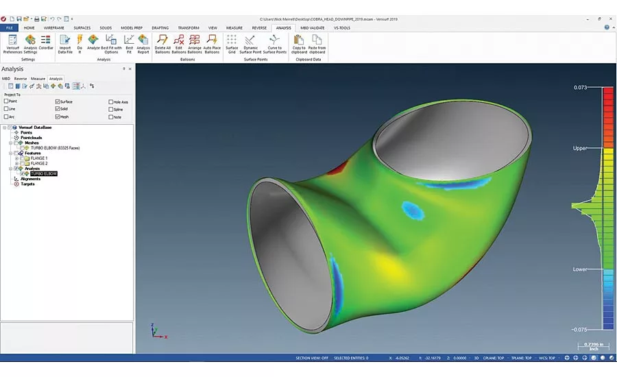
In the case of this software, reverse engineering is integrated with inspection, so the newly created surface can be compared to the original mesh to see how well the model conforms to the data.
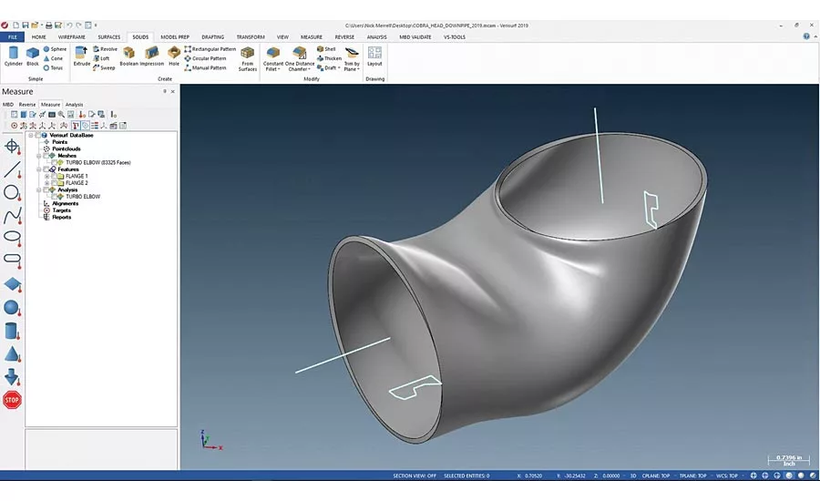
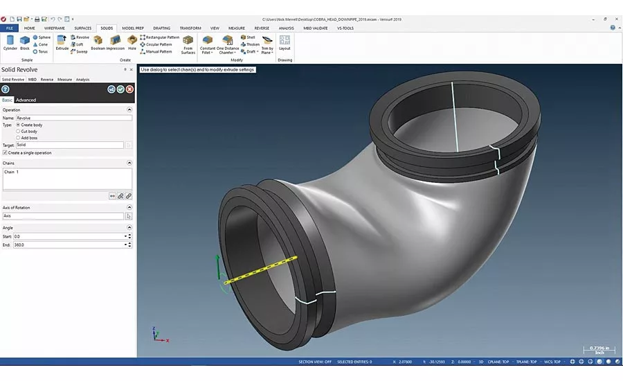
With the model confirmed it is exported to CAD to create the flanges, which were measured when the pipe was initially scanned. A Solids/Revolve tool is used to create flanges at both ends.
The completed intelligent solid 3D model can be used for CNC machining, flow analysis, re-engineering and inspection.
Today’s design and manufacturing world is quickly evolving to a model-based environment, one where intelligent 3D CAD models are the authority, containing not only the information to build a part or assembled product, but also to verify the end result against the nominal 3D CAD design. This reality requires more definition than ever before, expanding the role of measurement and reverse engineering software.
Model-based measurement and reverse engineering directly complement and feed the bigger concept of model-based definition (MBD). When deploying an MBD strategy the 3D CAD model becomes the basis for all information necessary to manufacture a part or product along with attributes for product lifestyle management (PLM). Everything needed to produce a part or finished assembly is included in the CAD model, from design to manufacturing, and all geometric dimensioning & tolerancing (GD&T) data. This maintains the all-important digital thread (aka the digital twin). The use of MBD can be far reaching and include many different attributes of a given part or product, including finish, coatings, colors, version control, statistical process control (SPC), and much more.
The complete MBD picture can be daunting for many shops to get their arms around, but for most jobs, model-based measurement and inspection are a great place to start as they are critical to virtually all implementations of MBD. A key benefit of MBD is that it removes ambiguity, conflict, and doubt that arise when drawings and models co-exist. With authority bestowed on the model, MBD eliminates errors that result from referencing an incorrect source and makes processes more efficient.
The term reverse engineering used to conjure up ideas of plagiarizing designs and intellectual property, but not anymore. Innovative techniques are being applied in virtually every aspect of the design and build process, from providing missing features or complex surface shapes to reconstructing legacy parts.
Common Reverse Engineering Applications
- Capturing organic and other complex surface profiles as part of the design process
- Recreating legacy parts during maintenance, repair and overhaul (MRO) that either lack CAD data, or are subject to stress causing the original part specification to no longer apply
- Scan-to-3D print applications
- Creating missing design features
- Determining best fit for components and assemblies, especially when there is a close tolerance envelope involved
- Comparing cast parts to the 3D CAD model in order to program more efficient machine tool paths and avoid tool crashes
- Analyzing large surface area parts for high points to modify tool paths, reduce machining time and eliminate cutting air
- Improving form, fit, and function of custom parts such as ducting and exhaust applications
- Recreation of an environment, such as the cockpit of an aircraft, for use in high-fidelity flight simulators
The list of reverse engineering applications is long and will continue to grow as engineers create new and creative ways to use the technology. The common denominator across the board is the need to capture highly accurate measurements and reverse engineer them back into intelligent 3D CAD models.
Reverse engineering software has come a long way, and many programs are extremely powerful, but the process requires a commitment to become proficient. Software tools that allow features to be extracted or have the ability to automatically identify extended surface areas are huge time savers, but users must understand the various workflows involved to be successful and should have a good working knowledge of 3D CAD.
Depending on the complexity of the part to be captured you will need a suitable coordinate measuring machine (CMM). There are many to choose from including portable or stationary CMMs equipped with a variety of contact probing systems or noncontact scanners. Contact vs. noncontact measuring is a popular question. To get the right answer you need to ask another question: how much data do you need to get the results you are looking for? Noncontact scanning is capable of capturing millions of points, creating very large point clouds, which is great but there is more overhead cost associated with processing large point clouds. On the other hand, touch probing, though more accurate, can take more time to capture enough points to create a good 3D model.
Reverse engineering software solutions differ in performance and tool set, but the overall challenge for each is the same. Measure points and point clouds using a probe or scanner, effectively edit the points into mesh and create 3D model surfaces and solid models for rapid prototyping, manufacturing and inspection.
1. Measure
A suitable CMM or scanner is used to measure and capture 3D features and surfaces as point clouds, including planes, cylinders, cones, spheres, lines, splines, circles and slots. As the term point cloud infers the collected data is a group of relative points in space without any connecting structure or geometry between them.
2. Mesh
The reverse engineering software will in essence connect the dots of the point cloud data applying geometry to create watertight mesh and STL models ready for surfacing and suitable for 3D printing. This includes alignment and merging of meshes, filtering, smoothing and filling holes. For some applications, like 3D copying, this is as far as you need to go.
3. Model
In order to work with the data as a 3D CAD model the mesh file must be converted into 3D surfaces and solid models. This is accomplished by the reverse engineering software, which can export the file to popular CAD formats to support precision manufacturing, guided assembly and automated inspection.
4. Inspection
Using the newly created, intelligent, 3D CAD model as the design authority, an inspection plan can be created to compare the original artifact against the model. Any errors, such as hole placements, fastening points or any other geometry can be updated in the model, including any additional intelligent GD&T callouts necessary for manufacturing or inspection. The newly reverse engineered model can now be used to generate CNC programing, and verify the quality of all subsequent parts.
Practical Example of Reverse Engineering
Some of today’s reverse engineering software applications include powerful processing and edit tools designed to expedite and improve reverse engineering. For demonstration purposes we’ve shown software that was used to reverse engineer an automotive turbo down-pipe, which is used to reduce exhaust gas restrictions and improve engine performance. Two-dimensional slice and edge spline tools within the software are an example of how software has evolved to quickly and easily create a surface from a mesh, a process that previously could be tedious and time consuming.
The part was measured with a laser scanner on a portable arm to capture the necessary point-cloud data that was then used to create a 3D mesh.
The open ends of the mesh are then exported to edge splines, which creates the first two curves that will define the surface. Next, the slice tool is used to create curves parallel to the ends and perpendicular to the flow axis.
With the curve network complete, a Net Surface tool is used to create a NURBS surface, rather than a collection of patches.
In the case of this software, reverse engineering is integrated with inspection, so the newly created surface can be compared to the original mesh to see how well the model conforms to the data.
With the model confirmed it is exported to CAD to create the flanges, which were measured when the pipe was initially scanned. A Solids/Revolve tool is used to create flanges at both ends.
The completed intelligent solid 3D model can be used for CNC machining, flow analysis, re-engineering and inspection.
Just as most companies standardize on a CAD/CAM platform, they should also try to standardize on a model-based measurement and reverse engineering platform, one that supports the necessary applications and can be utilized across the manufacturing enterprise. This will ensure consistency of operation, quality reporting, data management, and reduced training and support costs. Be sure the measurement software you select is open and offers the necessary level of interoperability to support your current and future measurement and reverse engineering requirements. Consider the following when evaluating solutions:
- Is the measurement and reverse engineering software based on a CAD platform, including 3D modeling?
- Does it import and export all CAD files and models seamlessly?
- Does it accept measurement data from all digital measuring devices?
- Is the software capable of controlling all digital measuring devices?
- Does it have the flexibility and embedded tools to handle a range of measurement data, from manual contact probing to noncontact point clouds?
Reverse engineering, as a tool and as a process, has evolved into an accepted and critical contributor to today’s digital design build workflow. Shops committed to model-based measurement should have a software toolset that not only includes reverse engineering, but also quality inspection and reporting, tool building, and assembly guidance.
Looking for a reprint of this article?
From high-res PDFs to custom plaques, order your copy today!


