Vision & Sensors | Optics
Core Concepts of Machine Vision Lighting
Proper lighting design is essential to assure a successful machine vision project. Ignoring this is one of the most common causes of machine vision project failures.
Source: grdenis / Creatas Video+ / Getty Images Plus via Getty Images
Machine vision lighting is a broad topic but a short article can be useful because some core concepts are not widely known. It’s been said “If you can't explain it simply, you don't understand it well enough,” so we’ll make an effort to leave out impressive math and jargon.
We’ll start with three core statements:
- The mission of machine vision lighting isn’t to “light it up,” it is to create reliable differentiation suitable to enable the intended inspection program to work. For conventional rules-based machine vision (vs. deep learning) the created differentiation generally needs to also be of “simple rule” type.
- Machine vision lighting design isn’t just about the light source. It’s a three-way geometric relationship between the light source, the camera or imaging system and the workpiece. Choosing a camera or workpiece location and orientation is often a part of “lighting” design, and the geometric relationship between those three items always is a part of lighting design.
- Proper lighting design is essential to assure a successful machine vision project. This statement goes beyond the routine platitude that it looks like; ignoring this is one of the most common causes of machine vision project failures.
Let’s simplify our discussion by narrowing it to 2D imaging and traditional rules-based (vs. deep learning) machine vision.
You already intuitively know some of the main concepts of machine vision lighting design, even if you don’t recognize them or apply them to machine vision. Let’s take a look at recognizing and describing them in order to apply them to machine vision solutions.
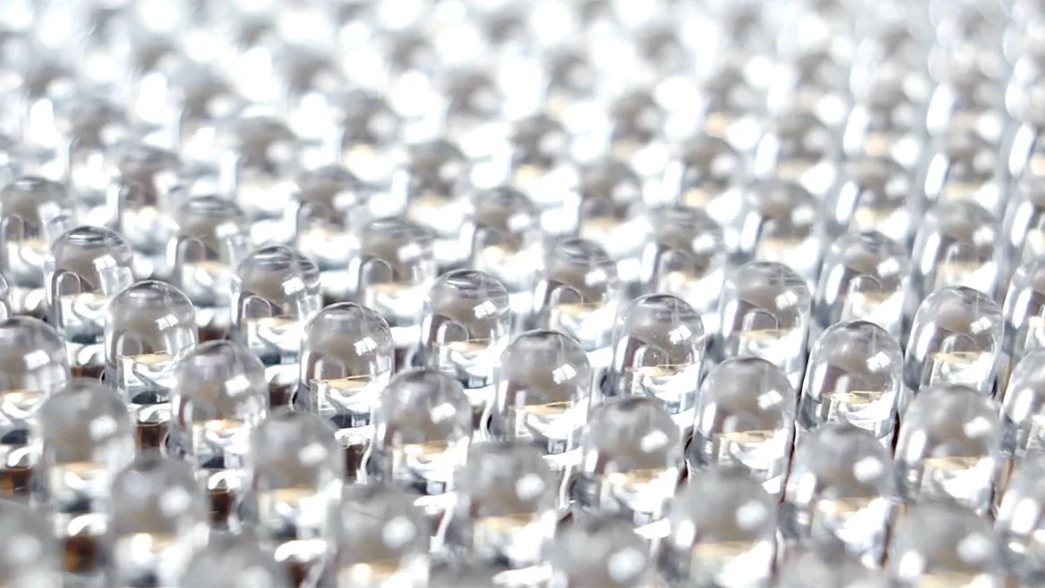
Figure 1 | Source: FSI Technologies Inc.
For our example, we’ll use the glossy printed item shown in Figure 1. We also introduced a defect: a crease/dent that goes through the yellow and orangish-yellow segments of the color wheel. The STAR acronym covers the four main fates of a light ray that hits the workpiece (Scatter, Transmit, Absorb, Reflect). Understanding and using those behaviors is at the core of machine vision lighting design. Scatter and reflect are the ones that we care about today and are shown in Figure 2.
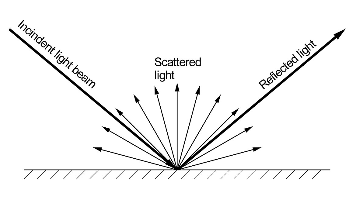
Figure 2 | Source: FSI Technologies Inc.
The flat portions of the shiny surface make part of the beam reflect in the opposite direction at the same angle as the angle of incidence. The reflected beam is very intense. The shiny surface behaves somewhat like a mirror. If you put your eye into the beam and looked at the surface, you would see an image of the light source rather than the product. A common name for that would be glare.
The dull card under the gloss converts the light into whatever color that portion of the workpiece is and scatters it in all directions. In any given receiving point, this scattered light from that spot is much weaker than the reflected light.
The first inspection mission is to measure the approximate length of the crease/dent that we put into the segment on the color wheel to see if it is severe enough to reject the product. While the lighting used for Figure 1 is nice by most standards, it is the worst possible lighting for this mission; it makes the dent completely invisible. But, if we handed you the card, you will intuitively know how to create a suitable lighting solution to accomplish the mission. You’d select a light source in the room with a large emissive area such as a 2’ x 4’ diffused ceiling light or a window letting in bright light from the outside. By holding the card flat, you can see the glare from the light source on it and you’d adjust it so the glare covers the entire area of interest. This adjustment creates ‘’simple rule’’ differentiation. That rule being, “the good areas light, the bad areas dark.” Your sight picture will look something like Figure 3 where glare covers the entire image. From there, your brain or machine vision program can easily separate the defect by lightness/darkness and evaluate it. The glare area is called a specular lighting solution.

Figure 3 | Source: FSI Technologies Inc.
You probably chose the optimal methods to create reliable, simple-rule differentiation for the dent, but there are others. One might be to bring light in at such a low angle that the dent creates a shadow for the area inside of it. This effect is one of the many meanings of the term “dark field.” Another method would be to place your eye/camera so there is no glare from the flat surface and rely on a shiny part inside the dent to be at the right angle to give you a bright specular reflection (Figure 4).
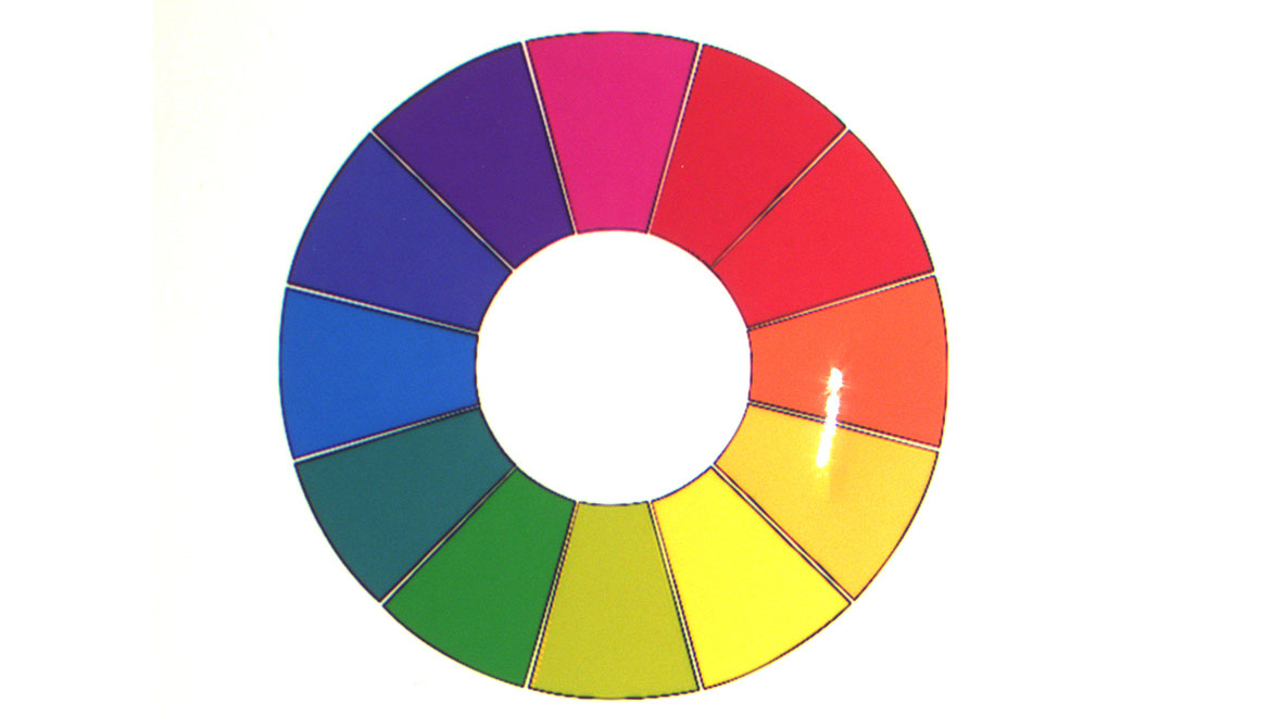
Figure 4 | Source: FSI Technologies Inc.
The second mission is to measure and verify the area of the yellow segment. To accomplish this, we need to separate the yellow segment from its neighbors. Thinking ahead, you’ll use color analysis software tools to do that. With casual random light, there are some areas of the workpiece that will have glare. Note how the colors in the glare area in Figure 3 are hard to see, which would make for a non-robust machine vision solution. If you were handed the card, you would intuitively create the proper lighting solution by moving the card so that there is no glare in the area of interest, making it look like Figure 1. Then your machine vision camera and software can easily separate, measure and verify the yellow area.
Here are three more tips learned from that process:
- As is commonly the case with the machine vision process, design starts with a later phase and works backwards from there. That doesn’t mean pre-designing the entire program. It does mean choosing the core method of the program that utilizes the lighting solution. For our examples, those are software tools that separate by color or lightness/darkness.
- In our main solution, we didn’t exactly see the dent. What we saw was an area where specular reflection from the flat surface was missing.
- What mattered most about the nature of the light source was its emissive area, the geometry of the area that is emitting light.
The flat surface made our color identification mission simple. The surface is all at the same angle so avoiding glare was simpler, and a flat surface does not create shadows on itself. For more complex shapes, these two effects become more difficult to avoid. One technique for those is to use an extremely diffuse light source where a low level of light is provided from all directions. A classic example is a dome light of the right size and placement. It behaves like a cloudy day outside, where there is no direct light from the sun and every piece of the sky is a lit-up cloud (a low-level light source).
What people know how to do intuitively they often don’t know how to apply to machine vision. One customer had a long-term problem reading characters on a glossy surface and sought an extra machine vision software training course to resolve it. We saw the image and replicated the problem, which was that someone thought that putting a ring light on the camera was a nice way to light it up which did the exact opposite of what was needed for the mission. We switched the light off, put a hardware store flashlight in the right place and their two-year problem went away. This further reinforces the importance of applying the underlying principles to lighting design. Hopefully this article has provided a useful introduction to some of them.
Looking for a reprint of this article?
From high-res PDFs to custom plaques, order your copy today!


