Measurement
Selecting The Right Solution For Shaft Inspection
Shaft measurement can be accomplished in many different ways, according to the needs of the manufacturing process.
All Images Source: Marposs
Shaft production has historically been, and still is, one of the most common processes in machine tool shops. Shafts are an elementary component of a majority of mechanical systems we use in our everyday lives and as the requirements of higher quality and precision of those shafts have become more restrictive, so have the requirements for inspection of the shaft’s features. Not so long ago, shafts were most often inspected using a variety of hand gages such as profile templates, calipers, micrometers or snap gages. Today, specialized shaft measurement systems better suited for modern shaft production processes are available.
In order to determine which type of gage is best for shaft inspection, various aspects of shaft production and features need to be considered, including:
The machining process being employed
Parts produced by different machining methods, be it turning or grinding, can require different gaging technologies. This is due to the different surface finishes produced, especially if you are considering a tactile measurement solution. Noncontact technologies work very well on finishing operations like grinding and polishing, but may not have the same accuracy or repeatability with rough turning operations, which can display burrs or rough surface finishes.
Production volume
Higher volumes generally call for a more dedicated, perhaps automated, solution that can measure quickly and provide feedback without affecting overall takt times. When it comes to lower volumes, a handheld solution or today’s flexible gaging systems can be practically and economically viable in many cases.
Part features to be inspected
Differing part features may require different technologies or techniques to ensure accurate and repeatable inspection results. For example, certain solutions may not be appropriate for measuring internal features such as keyways and holes.
Range of parts to be produced
The number of various parts being produced and the degree to which they differ will impact the design or type of inspection system that fits best in your process. These factors will influence how much flexibility is required within the measurement solution.
Frequency of part changeover
If you are changing production from one part to another several times a day, a flexible inspection system becomes much more valuable by eliminating downtime otherwise needed for mechanical retooling.
Ergonomic considerations
A gage is only useful if it is usable. The loading and unloading of the part, the sequence of measurement operations, and the operator interface must be practical and understandable. The inspection system must also deliver results that are not influenced by operator skill or bias.
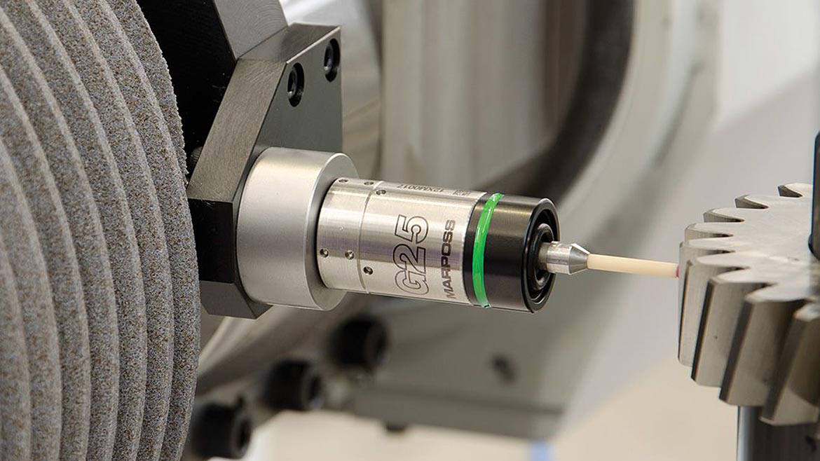
Optical scanning solutions offer noncontact optical scanning for rapid and accurate measurement and systems like this one can be combined with touch probes for inspecting for non-visible features.
A Variety Of Inspection Technologies
In the past, manufacturers were often forced to choose a dedicated system instead of a flexible one because flexible systems sacrificed accuracy or speed. Today, there are flexible gaging systems that can incorporate several contact and noncontact technologies in one system, giving you the ability to inspect a wide spectrum of features on a multitude of parts while sacrificing very little or nothing in system performance.
Some of the first flexible shaft measuring systems employed a tactile probe on a moving slide. In practical terms, it was a 2D CMM. The advent of scanning probes, which allow the system to collect hundreds or even thousands of data points per scan, helped to increase the accuracy as compared to discrete-point probe systems. Then 2D scanning probes further increased the flexibility of the system to include complex measurements such as gear tooth or spline geometries.
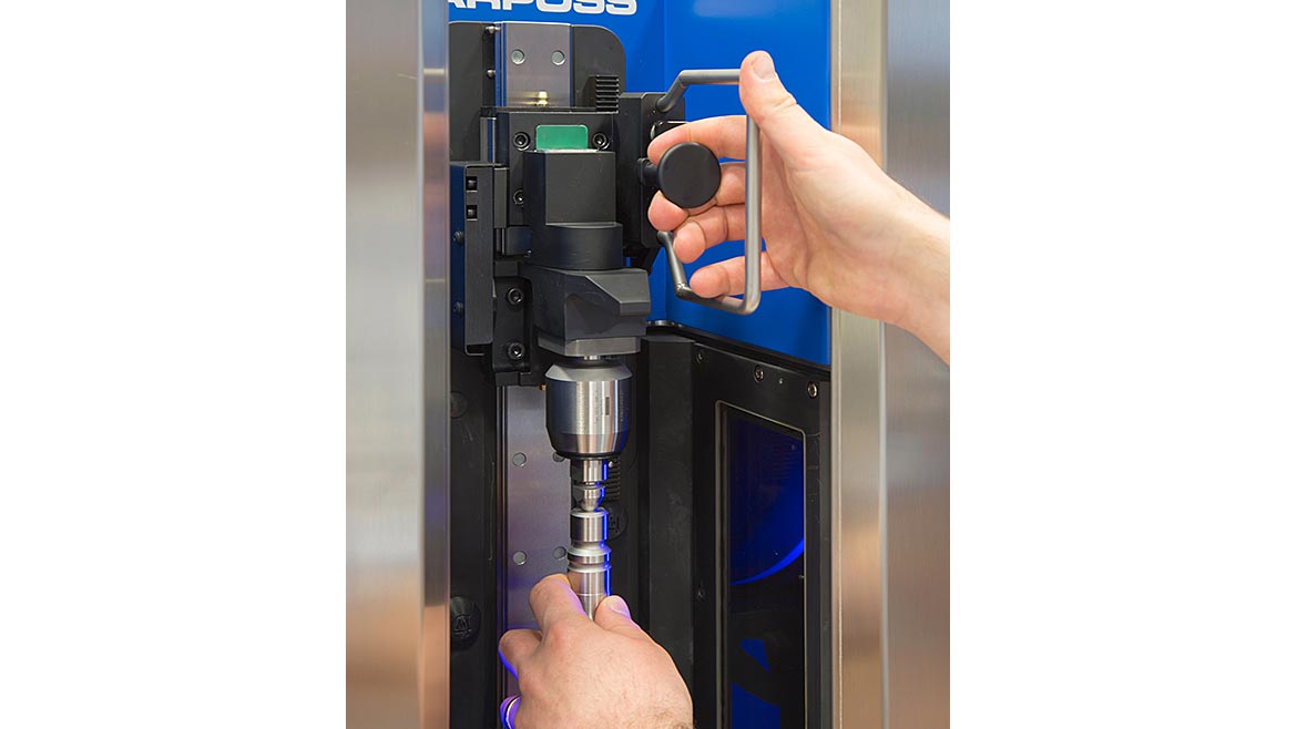
The Optoflash system offers optical measuring unit based on side-by-side 2D image architecture where images acquired by separate sensors are combined to form a single resulting image.
While highly accurate and flexible, the measurement cycles of tactile probe systems are often too slow to keep up with the production rates required, relegating the systems to the measurement lab or periodic audit inspections. In-process gages are still typically custom designed systems that required mechanical changeover between part runs.
Then came the optical gages employing CCD (charge coupled device), also known as matrix array, cameras or line scanning cameras. These devices project light across the part and analyze the silhouette that is created to measure the different part features. This method, often referred to as shadow casting, greatly reduces cycle times while adding even more flexibility for inspecting different shaft configurations. Optical measurement is not susceptible to the variances caused by tooling marks that can affect tactile measurement methods, so measuring parts with differing surface finishes is not as challenging as it once was. These systems also make it possible to inspect shaft configurations that are not strictly rotationally symmetrical. However, optical systems employing this method are limited to inspecting only features that create the silhouette. Features such as keyways and holes, not visible in silhouette, were not able to be measured.
Today, there are systems available that can use any of the above technologies along with others, such as lasers, for measuring the more complex features or high-speed following devices for rapidly inspecting eccentric diameters. These systems are capable of rapidly inspecting not only diameters and lengths, but many complex features such as chamfers, radii, threads, keyway slots, splines and others.
A big development is that advanced filtering routines in optical inspection equipment now allow these systems to be used in shop floor environments versus only within a lab setting, bringing improved measurement and efficiency to the process.
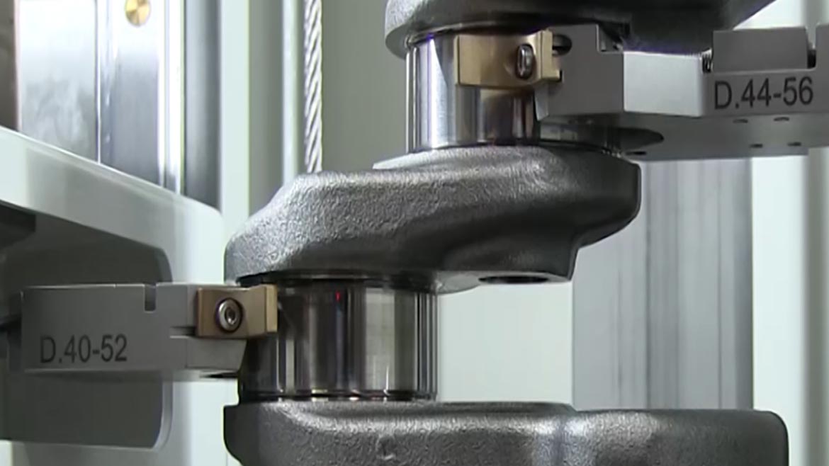
High speed tactile followers enable the inspection of eccentric or non-round diameters during high-speed rotation, including those with concave sections.
The Importance Of Software
Flexible and user-friendly programming allows you to customize your inspection routines for full production with automated loading and unloading as well as feedback directly to your machine tool for tool wear compensation while giving you the ability to also make periodic audit checks on certain critical features.
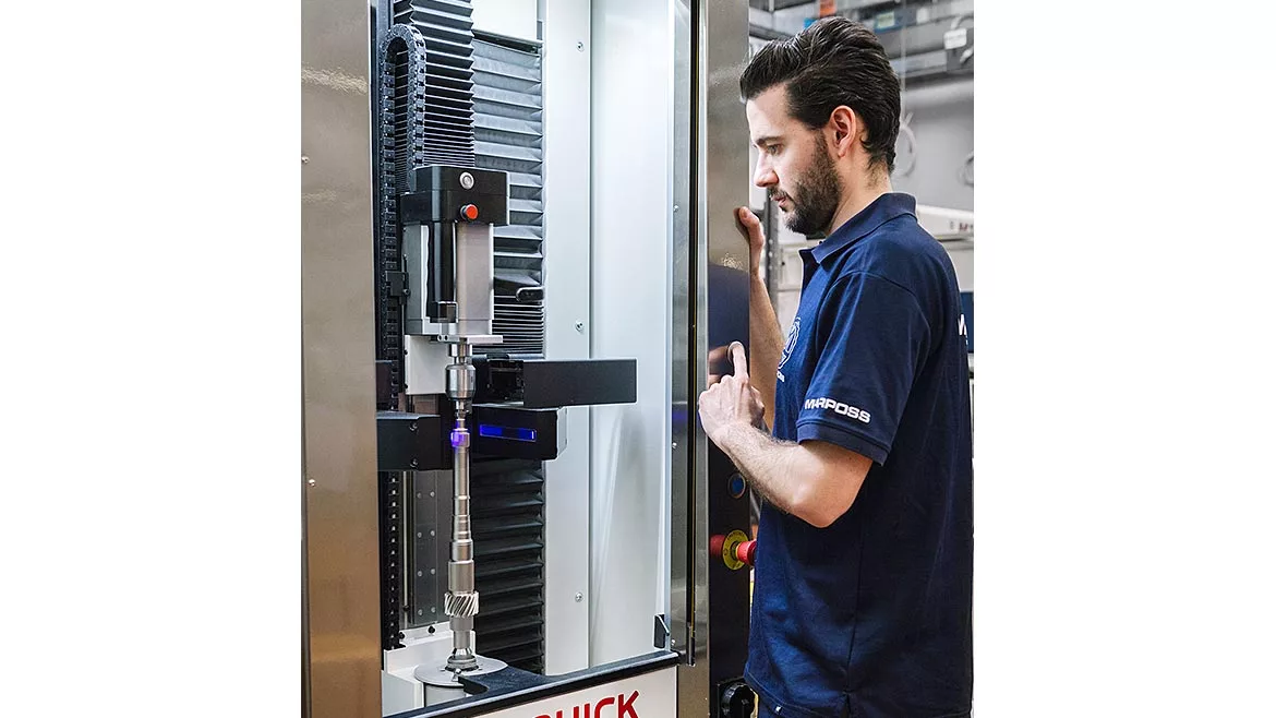
The measurement cycles of such systems when used in a manually loaded manner are usually semiautomatic, requiring only the loading of the part and selection of the desired inspection plan. Upon pushing the start button, the inspection is automatically performed and the measurement results can be displayed in a number of ways depending on the needs of the inspector. Graphic displays allow the user to zero in on part features of particular interest.
Shaft measurement can be accomplished in many different ways, according to the needs of the manufacturing process. Handheld devices such as micrometers are still used in many low volume processes, while highly sophisticated lab equipment is used in many metrology labs for periodic inspection and analysis. Tactile probe systems provide flexibility and accurate results, but often sacrifice speed for those features. Optical systems can be much faster but are somewhat limited in the scope of features they can inspect. Combination systems employ a variety of technologies in a single system to offer a high level of speed, accuracy and flexibility for your process.
For fast, accurate and flexible inspection on the shop floor, there are options available to meet the needs of any shaft production line. By considering the factors that define your process – and working with your quality solutions provider - you can make the right choice of system for your requirements.
Looking for a reprint of this article?
From high-res PDFs to custom plaques, order your copy today!


