NDT | Standards
How Pulsed Eddy Current Technology Helps Uncover Corrosion
The main advantage of PEC is that it can inspect through insulation, weather jacket, and wire mesh.
Source: GettyImages
The oil and gas industry continues to face the costly and challenging problem of detecting corrosion under insulation (CUI) or under fireproofing (CUF). If left unchecked, the consequence can be dire; the corrosion may cause a failure and even lead to a partial shutdown for safety issues it could potentially create. Data shows CUI as the leading cause of pipe leaks in past years1. Refinery operators must inspect their assets for corrosion as stated in the API 5832 standard. The usual workflow involves screening general areas where corrosion is suspected to be a critical problem, locally stripping the asset, and then using ultrasonic testing to measure the remaining thickness precisely. The problem resides in assessing the whole asset efficiently. In addition, stripping and reinstalling the insulation is not only expensive but also very time-consuming. Over the past two decades, many alternative inspection methods have been used to tackle this challenge. The one that became recently popular for its outstanding results? Pulsed Eddy Current, or PEC.
Over the last few years, PEC has been developed and improved for much more productive and reliable inspection of a wider range of components. Because of these new developments, PEC is a very cost-effective option for the corrosion screening of several components while in service. Recent technological advancements in PEC made it more reliable, so much so that PEC was included in the 2021 edition of the ASME boiler and pressure vessel code and ISO3 "Non-destructive testing — Pulsed eddy current testing of ferromagnetic metallic components". To understand how PEC has become a widespread inspection tool in the oil and gas industry, let’s start by first reviewing how it works.
A PEC probe contains coils through which it circulates a short pulse of current. The pulse duration is specifically chosen to produce a stable magnetic field that is strong enough to penetrate the whole thickness of the material. This is called the emission phase and can last a few milliseconds to hundreds of milliseconds, depending on the material’s properties and thickness.
Once the magnetic field reaches a steady state through the material, the current in the coils is abruptly turned off. The variation in the magnetic field induces an eddy current in the pipe. Those eddy currents will in turn generate a magnetic field that the probe’s coils can measure. The resulting signal will decay over time: the thicker the pipes, the longer it takes for the signal to fade. Specifically designed algorithms analyze the decay of the eddy current and correlate it with the remaining wall thickness.
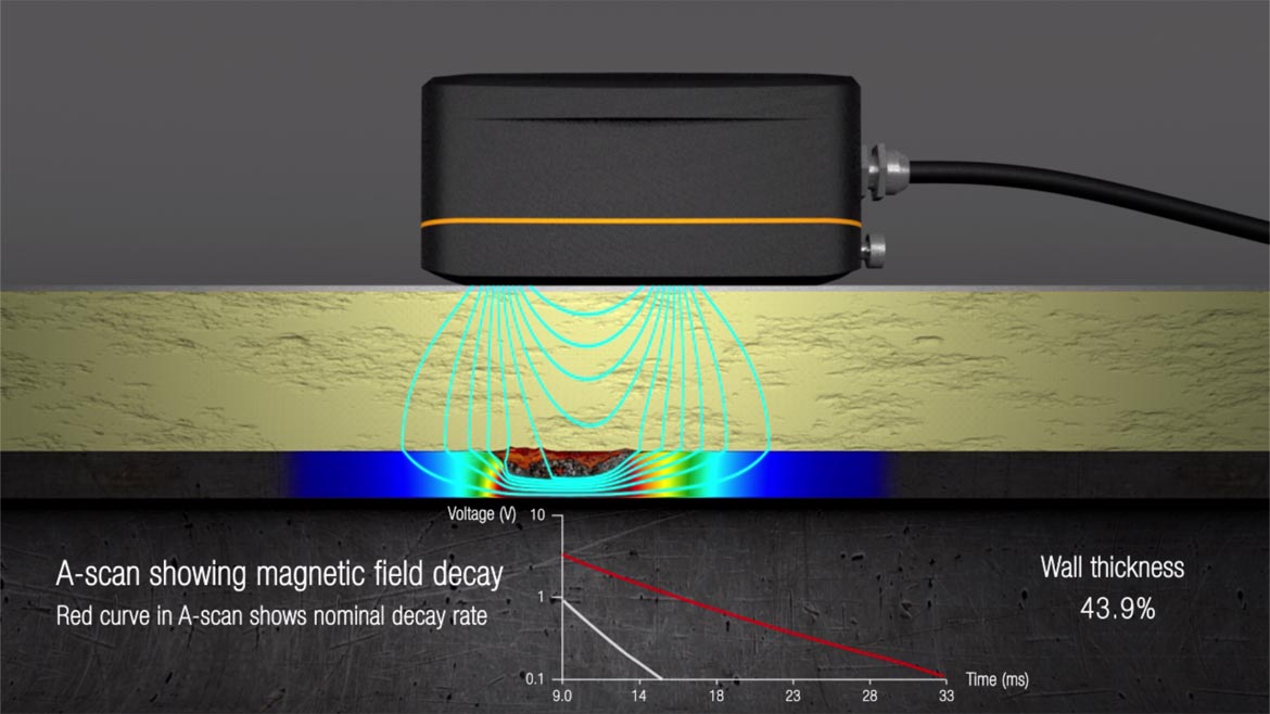
Figure 1. Magnetic field decay rate is reduced when wall thickness is less than nominal. | Image source: Eddyfi Technologies
The main advantage of PEC is that it can inspect through insulation, weather jacket, and wire mesh. This is a significant advantage for CUI and CUF inspection since there is no need to strip the insulation or shut down assets, making it less costly and more time effective. PEC can inspect through several inches of insulation and is remarkably tolerant to lift-off variation caused by sagging, for example.
A PEC probe can tolerate a lift-off up to approximately 12 inches by using very large coils that produce a magnetic field that is proportional in size. A large magnetic field also means a larger energized area under the probe. The signal measured by the probe is an average of that area, which limits the detection of very small or shallow defects, such as pitting. The further away the probe is from the component, the larger the coils need to be, so when you get more lift-off, the detectable flaws get bigger.
Some aspects of wall thickness measurement with PEC are important to understand. First, the wall thickness value given by PEC is not absolute; it is a relative measurement based on the nominal wall thickness of the component. Moreover, PEC reads information related to wall thickness only; it won’t tell if wall loss results from near or far side corrosion, although inspectors usually know the dominant damage mechanisms in context. Finally, the eddy currents are also sensitive to the electromagnetic property variations of the inspected materials. For instance, pipe manufacturing processes and alloys can induce such variations, which is the main reason why PEC wall thickness measurement accuracy is around ±10% of the actual nominal wall thickness. For those reasons —and despite continuous technological improvements to increase inspection performance and accuracy— it is recommended to use PEC as a screening tool to find corrosion quickly and economically with a reasonably accurate wall loss measurement.
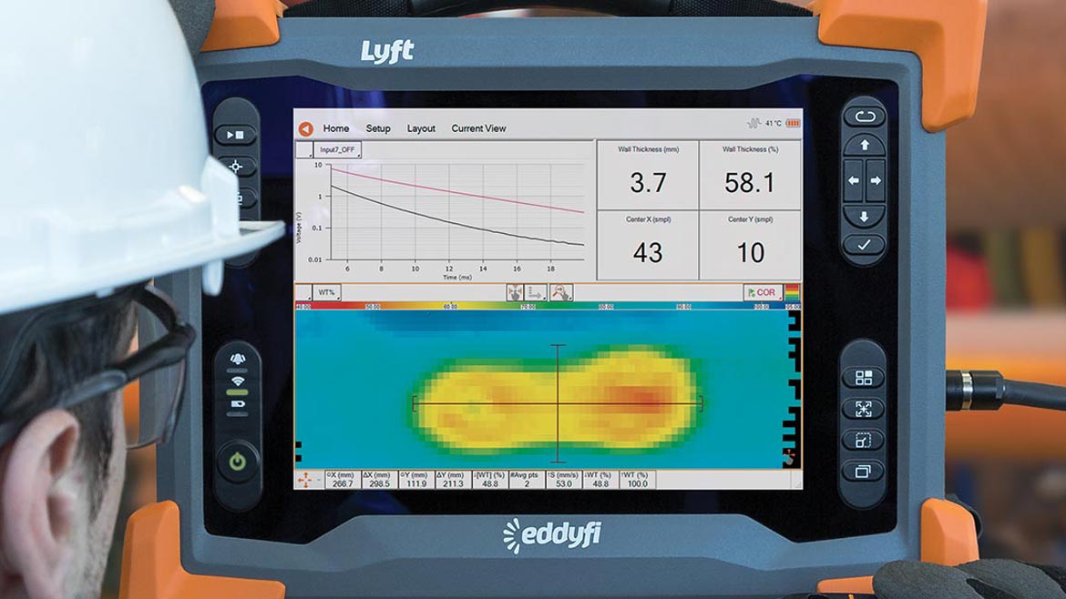
Figure 2. PEC inspection system with probe on a pipe with corrosion scabs. | Image source: Eddyfi Technologies
When wall loss of concern is detected and measured with PEC, verification of the area should be carried out using a secondary and more comprehensive technique.
Pros and Cons of PEC
- Inspect through 12 inches of lift-off (insulation, fireproofing, etc.)
- Measure thickness of carbon and cast-iron steel up to four inches thick
- Easy and fast to deploy
- Measurement accuracy ± 10% of the nominal thickness
- Detect outer and inner corrosion
- No surface preparation required
- Measurement affected by flanges and edges
- Cannot detect small and isolated pitting
Knowing the advantages and limitations of PEC, let’s now look at how it can be integrated into a risk-based inspection process and for which assets it is more adapted. First, PEC’s ability to quickly identify corroded areas before the planned shutdown period allows inspection of a wide array of assets at a high frequency without significantly affecting work schedules. Furthermore, knowing the location of generalized corrosion beforehand improves the efficiency of quantitative methods such as radiography and ultrasonic testing (UT) during shutdowns, as they can specifically target these areas.
Let’s now look at two examples showing the cost and delay related to this inspection method. First, let’s study the inspection of Horton sphere leg inspection. These pressure vessels are supported by steel legs covered by a fireproofing material. Removing the fireproofing layer over the entire surface of the legs represents 80% of the cost of a traditional inspection procedure. Instead, using PEC to screen for corrosion and then only removing the fireproofing for further assessment locally is roughly four times less expensive. In this example, data from PEC shows an area of suspected corrosion with no visible cracking or rust stain in the concrete. Yet removing the fireproofing locally exposed the damage’s extent, as shown in the following picture.

Figure 3a. PEC Data detected a suspected area of corrosion. Removal of the fireproofing material revealed the extent of the damage | Image source: Eddyfi Technologies
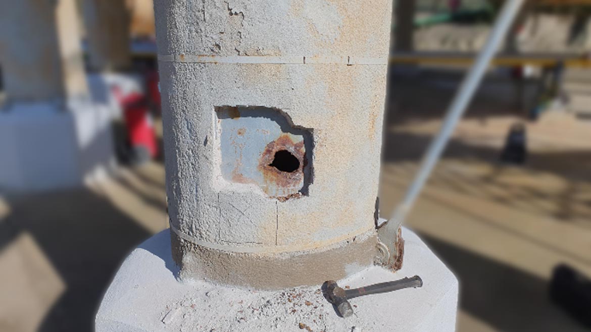
Figure 3b. PEC Data detected a suspected area of corrosion. Removal of the fireproofing material revealed the extent of the damage | Image source: Eddyfi Technologies
The cost and time saving for inspecting pipes are also quite significant when using PEC instead of stripping the insulation to screen for corrosion. For our example, let’s take a pipe with a nominal diameter of eight inches with two inches of insulation and 0.02 inches aluminum cladding. In this situation, a PEC system can screen between around 500 to 650 feet daily. With recent technology developments, the scan is made dynamically, thus removing the need to fully grid the pipe. Furthermore, the PEC probe now contains an array of multiple coils for increased coverage and higher productivity.
In summary, PEC’s main advantage is its ability to inspect corrosion without the need to remove the insulation, fireproofing, or weather jacket. It can thus be used as a cost-effective method to screen for detectable corrosion, including generalized corrosion. Instead of stripping entire assets, PEC makes it possible to target local areas for further investigation. This makes PEC an efficient and economical tool that allows assessing the condition of additional assets in a shorter delay. This notion of screening multiple assets aligns with a risk-based inspection as described in the API 5814. Of course, PEC has advantages but also limitations and understanding them is key for successful use of this method alongside complementary methods such as UT. Recent technological advances in PEC have made the technique a fast and reliable method helping refinery operators increase the reliability and safety of their assets.
RESOURCES
1 Brian J. Fitzgerald, Corrosion Under Insulation And Best-Fit Solutions, Inspectioneering Journal, https://inspectioneering.com/journal/2014-08-27/4125/corrosion-under-insulation-and, 2014.
2 API (2014), "Recommended Practice 583: Corrosion Under Insulation and Fireproofing", first edition
3 ISO, 2017, "Non-destructive testing — Pulsed eddy current testing of ferromagnetic metallic components" (Geneva, Switzerland: ISO)
4 API (2014), "Recommended Practice 581: Risk-Based Inspection Technology", first edition
Looking for a reprint of this article?
From high-res PDFs to custom plaques, order your copy today!


