Diameter Measurement
How to Measure Big IDs and ODs
As with any diameter measurement, there are several possible solutions.

All Images Source: Mahr
Imagine your task for this week is to develop a hand tool gaging solution for a large rotor with an ID of nearly 400mm. Given the size and the large diameter, it is unlikely the part can be brought to a gage or even a CMM for an in-process check. Instead, the diameter will need to be measured at the point of manufacture. One could typically use an adjustable bore gage or an inside rod micrometer to check the large diameter. However, this part has a hub in the center of the diameter to be checked and presents an obstacle.
As with any diameter measurement, there are several possible solutions, usually tolerance based. Once a diameter approaches this size, the tolerances are relatively loose, providing several potential options. There are even solutions for a large precision diameter. This article will examine the scope of gages that have the potential to solve this requirement.
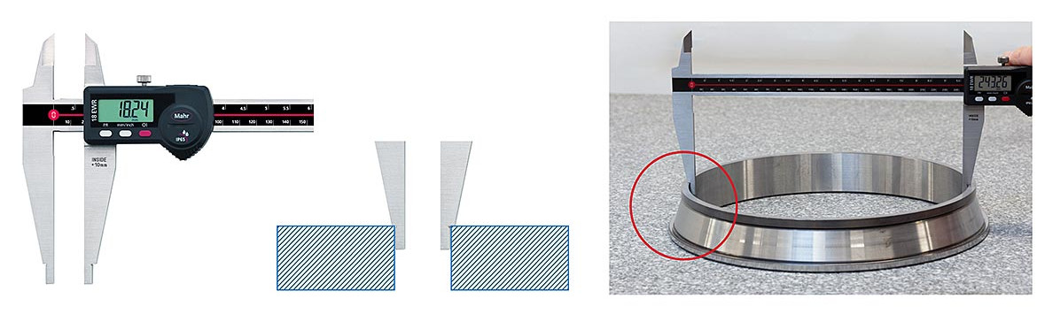
The jaws on large Digital Calipers allow for measuring IDs while providing a reference surface allows the caliper to sit square to the ID.
Large Calipers
A large digital caliper could be considered if the diameter is a type going to the edge of the part. Calipers over 300mm tend to have jaws with an OD radius set of contacts machined into them specifically for this purpose. In fact, the radius also has a shoulder which allows the jaws to sit in the diameter on the face to square up the measurement and provide easier alignment for the user.
Since this is a two-point measuring system—and even though the shoulder on the jaw acts as a reference to set the measuring depth—this whole family of hand tools requires a specific operator skill. This is because to get the true diameter, the gage must swing through it, searching for the largest value for the ID. So typically, the reference contact is held in place while the sensitive contact (with a little force by the operator) is held against the part diameter and the value observed.
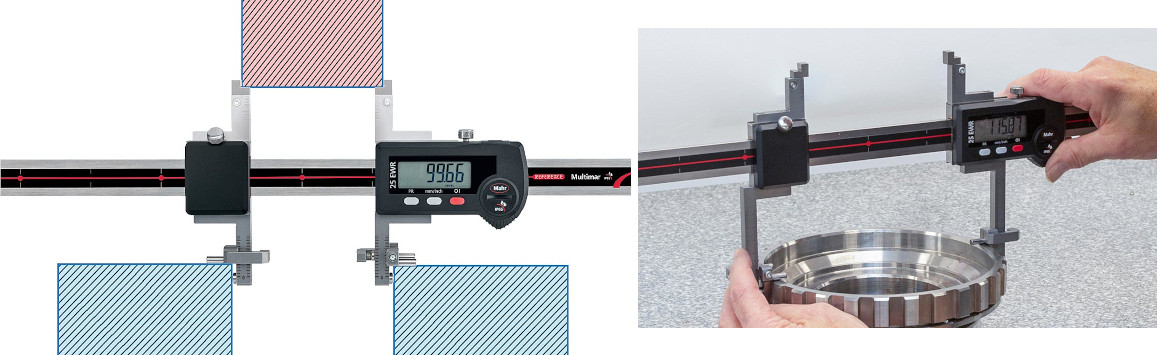
Some caliper style ID/OD gages allow for using two sets of jaws at the same time - allowing one setup to make two different measurements.
ID/OD Calipers With Interchangeable Jaws
If the diameter is not on the edge and there is a need to measure deeper into the bore, or even a groove within the diameter, a universal ID/OD caliper may be a way to make this measurement. These types of gages employ a caliper-style beam or long rail. With the caliper style ID/OD gage, the fixed and sensitive jaws are interchangeable with a whole series of options to dedicate the gage to the measuring task. In addition, there may be mounting available to place another set of jaws on the top and bottom of the sensitive and measuring slide. This allows the caliper to check an ID and OD with one setup.
Basically, these are large specialty digital calipers and offer some benefits for this type of check. Because calipers are measuring instruments, the reference is built into the scale, and no external masters are required. But also because they are calipers, the digital resolutions (typically 0.01mm/.0005") over the long-range are not typically meant for higher accuracy requirements. Combine this with the operator skill required for searching for the diameter on a moving scale, and the chances of error are pretty significant. On the other hand, since they require a specific master for the measured size and have an extremely long measuring range, versatility presents a valuable feature. As a result, these digital and ID/OD calipers offer good value when roughing in a diameter or general inspection requirements.
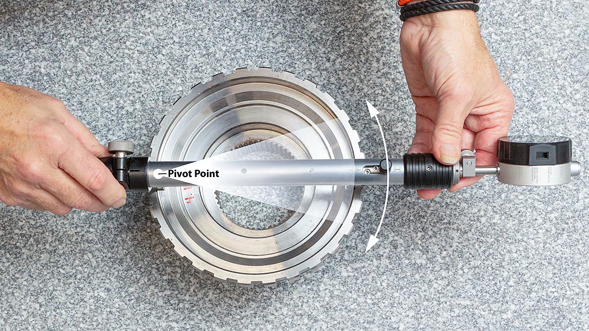
ID/OD calipers and comparators require the user to "swing" the gage through the diameter and search for the largest reading when measuring the ID.
ID/OD Comparative Gages
The same two-point concept can be used to get to the next “better” level of checking the large diameter but moved to a comparative version of the hand tool. Rather than having the scale built into the gage as with the caliper, an external master is used to compare the measured diameter. This is no longer a direct measurement of size but rather a comparison to determine if the part is larger or smaller than the setting master. This comparative hand tool has a limited measuring range but can offer higher resolution and very good accuracy over a short measuring range.
Many gages have capacities starting at 25mm and reaching over 1,000mm. Depending on the size, they may have adjustability from 100mm to 400mm. On some gages, rails of different lengths may be interchanged, so the adjustment range is virtually unlimited. With many interchangeable jaws and contacts available, ID/OD universal bore gages are adaptable to a wide variety of applications, including grooves, tapers, cylinders, and features recessed behind blind shoulders.
Like the digital or ID/OD caliper, the ID/OD gage must be rocked or swept through the bore to find the true diameter. However, these gages offer an advantage over the caliper-type version because they employ a spring-loaded sensitive contact. The operator must hold the reference contact to the diameter with the caliper-type instrument. Then, while applying force to the measuring contact and sweeping through the diameter simultaneously, the user looks for the max values. A lot of hand coordination is required to get the result. With its spring-loaded sensitive contact, the ID/OD comparator makes this measurement much simpler for the user.
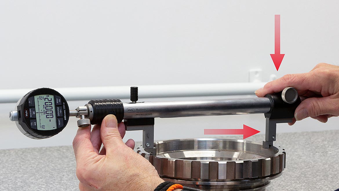
Apply enough force both down and against the ID reference arm to lock in the reference contact.
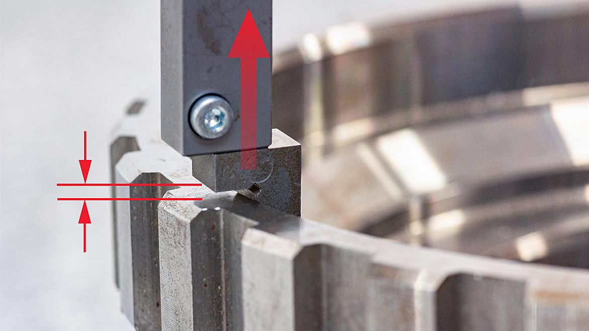
Slightly lift the sensitive contact to reduce downward forces so that the gaging pressure of the gage can easily find the high point when searching for the diameter.
Jaws For Every Purpose
Just like with the caliper version of the universal ID/OD gage, interchangeable jaws, and contacts allow for a wide variety of measuring applications. Most interchangeable jaws employ a depth stop built into the jaw or an additional adjustable stop to set the depth of the measuring contact. This stop takes one degree of motion out of the measurement, making alignment easier for the operator. Though some technique is still required by the operator, on the reference side of the gage, the contact acts as a reference, and the height stop sets the depth – thus, a two-point location reference. On the measuring side, with the sensitive contact, there is the gaging force, but friction is also being applied to the depth locator by the weight of the gage. Since these are large gages, the weight of the gage could be larger than the gaging force of the sensitive contact. So, the operator must ensure the reference contact is secure while sweeping the ID for diameter, but at the same time, very slightly lifting the sensitive jaw to take the pressure off the depth stop so that it does not influence the operation of the sensitive contact. This is not a very hard operation for the operator, but one that is critical to the performance of the measurement.
Common jaws can be used for simple shallow bore IDs (with radius contact) and similar contact but with flats for OD checks. There are similar jaws allowing for a depth of 100mm or more with interchangeable ID/OD contacts to reach deeper into the bore. For gages offering more than 100mm of depth capacity, special bracing or heavier contacts are required to provide the necessary rigidity. The contacts are usually back-tapered to ensure accurate point-to-point measurements. Adjustable stops are added to the jaw to set the gaging step to help stabilize the gage. These are especially useful when the ID is a groove or slot within the ID and allows for precise, repeatable positioning of the contacts or the user.
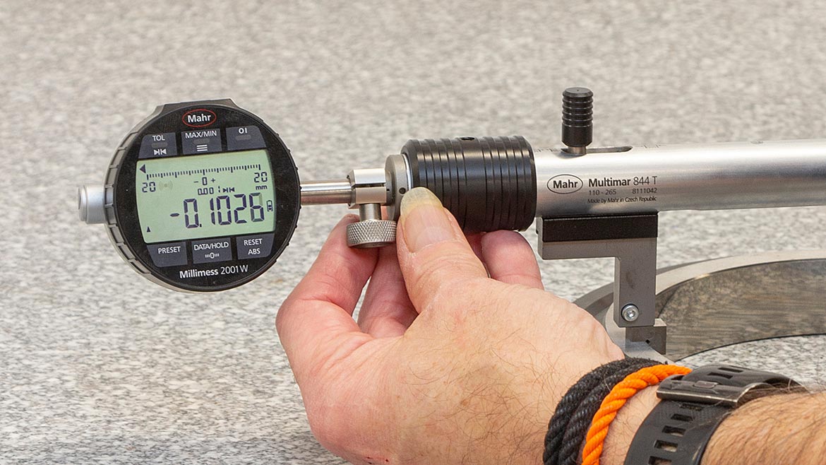
High performance digital indicators will greatly reduce operator error and performance with features such as dynamic Max readings, high resolution and analog/digital display along with wireless connectivity.
Improving The Search With Digital Indicators
Because the measured diameters are usually large, dial indicators with a resolution of 0.0001” or 0.0005” are typical. Higher-resolution indicators, digital indicators, or even electronic transducers can be substituted for applications requiring higher resolution or data output. Because the ID/OD gage is a comparative instrument, it has a large adjustable range but usually a very short actual measuring range. Because of this, these gages are more likely to use a digital comparator than a digital indicator. In addition, their electronic readouts have dynamic memories built in, providing the ability to automatically capture the “min” or “max” value during the sweep. This is a preferred means of reducing operator errors—dramatically improving the results using the comparator’s higher resolution and accuracy.
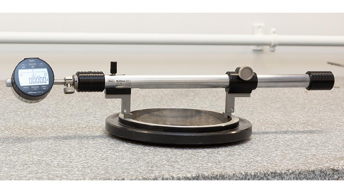
A certified master ring is most likely the best way to set a comparative ID/OD gage.
Mastering For Precision
With the caliper or ID/OD universal caliper gage, it may be possible to set a zero by touching the contacts together since the “reference” is built within the caliper. However, for long-range calipers, this built-in scale has errors that build up over the measuring range. Because of these errors or because the application cannot set a reference with the contacts, an external standard will be required.
Using an outside micrometer may be the quickest and most available method for the smallest sizes, but there are issues with the accuracy of this setup. Micrometers have inherent errors that can be passed along to the gage. Another significant issue is accurately locating and aligning the gage’s spherical measuring points on the contacts of the micrometer. While readily available and inexpensive, this setup method probably offers the least accuracy, which must be compared to the part tolerance to see what portion is consumed by inherent error.
The best method for setting the adjustable bore gage is with a master ring or disc. This duplicates the actual measurement, and masters can be made to the specific part size. Most ID/OD universal gages have a flat surface on the jaws that allow the gage to be placed and set on the master ring, supported by itself. Using this method, the ring is laid on a granite surface plate, the ID/OD universal gage is set in the ring, which will support it, and the sensitive contact is adjusted until the indicator reads zero. It is even possible to use a ring gage that is not exactly the nominal size, as the offset can be incorporated into the set of the digital indicator as long as the master is within the range of the sensitive contact. A ring gage is preferred for setting repetitive sizes or when an adjustable bore gage will be dedicated to a particular size. The downside of this method is the potential cost. Rings can be expensive, and the total cost may be prohibitive if one is required for each of the many sizes on the shop floor.the diameter is an economical way to set a wide variety of gages with minimal investment.
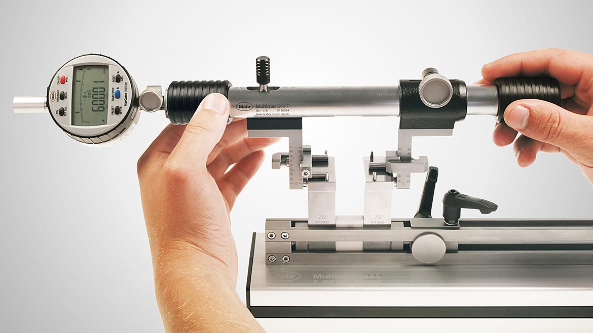
A Universal Length Setting fixture using gageblocks to set the diameter is an economical way to set a wide variety of gages with minimal investment.
Using a gage block assembly in a clamp with jaws at both ends will also provide a highly accurate reference master. This may be the preferred method when multiple sizes are required, and flexibility is critical. Gage blocks are the most basic reference standard. They are readily available and provide high accuracy. The only drawback is the time required to assemble the gage block stack to the nominal size. Also, since only a single stack is used, there is no verification that wringing errors have not been made in assembling the stack, and although small, these could affect the performance of the gage.
Care must be taken when setting any gage to its nominal size. The setup of the master or gage block is critical. This means they must be clean and free of dirt. Also, they need to be temperature stable, as does the gage.
Once the reference contact is set to the desired size, the locking screw should be made snug, and the gage tested again for zero and repeatability. If nothing has changed, keep snugging down the locking screw until it is locked into position. Then recheck the repeatability until you are confident that the gage performs accurately.
Conclusion
Measuring large IDs and ODs at the point of manufacture will always be a challenge. In many cases, as the diameters get larger, the tolerance increases, allowing for the use of calipers and comparative ID/OD gaging as described here. Should the large diameter have a tolerance beyond the scope of the handheld tools, then a dedicated variable fixed plug or ring gage may be required.
Looking for a reprint of this article?
From high-res PDFs to custom plaques, order your copy today!


