Air Gaging Moving Forward Faster Than You Think
Let's look at how air tooling and its accessories are moving into today's modern manufacturing processes.
All Images Source: Mahr
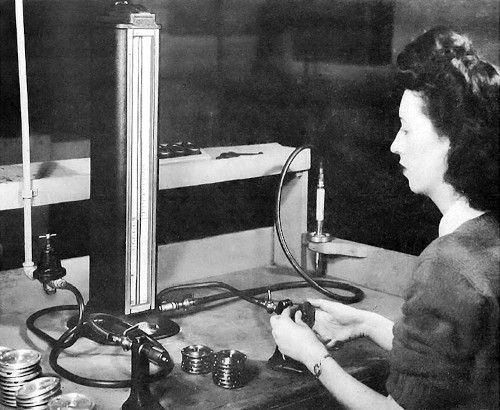
In the ‘40s, air gaging might have been considered the greatest thing since sliced bread. While sliced bread was busy becoming mainstream, air gaging brought just as exciting a breakthrough to the shop floor. You see, at this time—long before electronic probes and amplifiers—it was very difficult to achieve a 50u”/1um resolution on the shop floor. The most common readout used at the time was dial indicators or dial comparators. However, being mechanical, they had issues when used at the point of manufacture, including wear, repeatability, contamination, lack of robustness, etc.
When air gaging was introduced, it provided the first high-performance 50u”/1um or better gaging on the shop floor. In fact, air gaging provided two breakthroughs for dimensional measurement. The one most of us are familiar with today is the use of small orifices or jets built into tooling and used for dimensional comparison. The other and often forgotten technology was the air probe—a contact probe very similar to the LVDT probes common today—but functioned by the contact tip of the probe opening and closing a tapered valve in its body. About 30 years ago, this technology began to be replaced by LVDTs/digital probes/digital indicators that were becoming more robust and economical.
However, the jetted air tooling introduced in the ‘40s was just as important to precision manufacturing then as it is today. The fundamental reason air gaging will continue to be a key measuring method is the air jet itself, the small orifice through which air creates the physical conditions for measurement. It is hard to imagine that a small hole, less than 0.050/1.2mm in diameter, could be so important. Yet, there are no other gaging sensors as small or that can be placed so close together to measure multiple diameters or geometric forms.
Being a collector of old original catalogs and marketing material for air gaging, it is remarkable to see that the same selling points, along with the same tool and application configurations, have not changed in the 80 years since its introduction. In fact, if one could find an air plug from the ‘40s in good condition, it would probably still work with a manufacturer’s air gage recently made display.
Basically, since air gaging is based on the laws of physics and fluid characteristics, these laws don’t change. An air gage works on the principle of back pressure, which occurs when a solid surface restricts pressurized air from the jet. Today’s air gaging systems still use this pressure phenomenon to measure distance. But, of course, an air jet is more than just a small hole. It is really a precision hole created with many knowns: its size; a controlled surface around the jet; a known depth from the surface of the tool holding it; and a built-in air escape system.
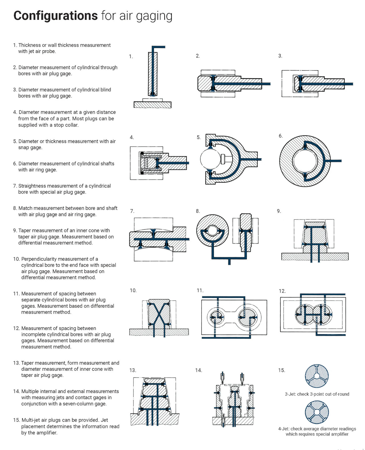
The configurations for air gaging chart below shows many types of relational checks that a combination of air jets can perform. In some cases, the air jets can be combined pneumatically to perform the measurement, as with an air plug. But each jet also can be combined in an external processor to measure diameters, tapers, bend, and twist from the same jets. This type of chart can be found in air gaging catalogs going back decades.
So, while the tooling portion of air gaging and the laws of physics have stayed the same for decades, what does change?
From the user side, there is an increasing demand for shorter lead time on tooling and master supply, longer-wearing tools, and more versatility, features, and value in the displays used to get more information from existing or new tooling. Let’s look at the advances in how air tooling and its accessories are moving into today’s modern manufacturing processes.
Materials And Coatings
Air tooling is designed for use on the shop floor in some of the harshest manufacturing environments, often measuring countless numbers of IDs, ODs, and lengths over the life of the part manufacturing cycle. Air gaging is also used for measuring pump barrel rods or in automatic gaging operations where millions of cycles are common.
Air tooling was initially manufactured from hardened tool steel. This offered acceptable life, and rust would not be an issue if used with residual oils from the shop floor. But store that plug for a few months, especially in a humid climate, and the chances of pulling it from storage showing signs of rusting would be typical.
Enter chroming the tool. Chroming became a popular and widely accepted method for two reasons. First, chroming helped to prevent rust and was often required when the tooling was going to a hot and humid region. Second, chroming dramatically increased the wear characteristics of the tooling.
While these are great features for the user, in today’s world, it is not a great option for the manufacturer or the environment. In addition, chroming is becoming expensive to control, and many towns and states will soon likely ban chroming operations completely.
In its place are two advances that solve these issues and often provide shorter lead times and improved products. The first is manufacturing the tooling from hardened high chrome content stainless steel. The high chrome content stainless approaches the same characteristics of chromed tooling. It helps to prevent rust while providing long life for the plug.
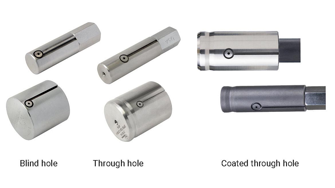
Also, as an alternative to chroming, tool life can be extended with a new, physical vapor deposition AlCrN-based coating that offers superior wear characteristics, ideal for improving the life performance of air tooling in production environments. This vapor disposition is like the coatings offered on machine tool cutting bits for an improved life. The new coating replaces the environmentally harmful chrome plating previously used for high-wear applications. It provides excellent hardness and shock resistance.
These coatings also offer a rich dark grey color that distinguishes the new plug in appearance. Even in high humidity, it enables superb wear and rust prevention results. This coating option offers the user of air tooling far superior longevity for high-usage applications.
New Manufacturing Processes For Faster Response
While users of air tooling probably do not care specifically how their air tool is manufactured, they are concerned about how fast they will get it when a new job comes along or when existing tools show signs of wear requiring replacement. The tool’s value is seen not only in its initial cost but also in its delivery speed.
Air plugs and rings, basically round pieces, are most likely produced on lathes, whether manual or CNC. Since every air tool is custom-made for the application, the manufacturing processes are pretty much the same—turn the bar stock and drill the holes needed for the jets and air passages.
There are few advantages in high-volume manufacturing with air tooling. However, there are ways to reduce machining steps and part handling for standard air tooling configured using known standard design specifications. By utilizing the computing capabilities of today’s manufacturing machines and developing intelligent parametric part programming, air tooling can be manufactured in one single operation by a user keying in four separate part parameters to produce the standard air plug more efficiently. The result is shorter lead times and faster deliveries to customers. Even if quantities of tools are required, parametric part programs significantly reduce the manufacturing cycle to enable faster deliveries.
It’s An Analog World—Well, Maybe Not For Long
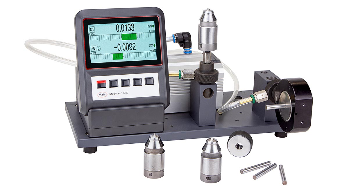
Air gaging was introduced long before digital displays. The original display consisted of water levels in glass tubes, a bobbin floating in a tapered glass tube, or some form of a mechanical-based analog dial. Most air gaging is still based on the magnification derived from the actual length of the analog dial compared to the movement seen by the air tool. Thus, the typical magnification referred to on a lot of air tooling, such as 2500:1 or 5000:1, for example, comes from the analog dial’s length.
Related Articles
Why the different magnifications? Well, again, it comes from the characteristics of analog readouts. With analog dials, you can have “long range and low resolution” or “short range and high resolution.” This characteristic matched nicely with part tolerance—as the tolerance gets smaller (less range), one typically would want higher resolution (higher magnification). As with dial indicators, the goal is to have the tolerance be approximately 20% of the dial, and magnification was chosen based on this.
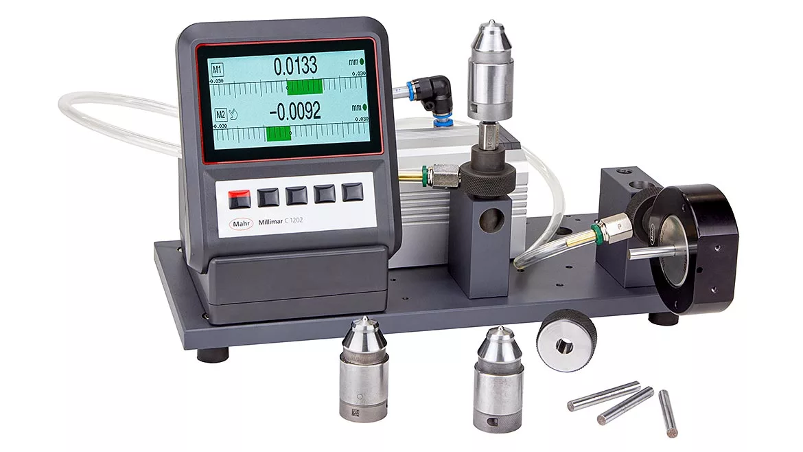
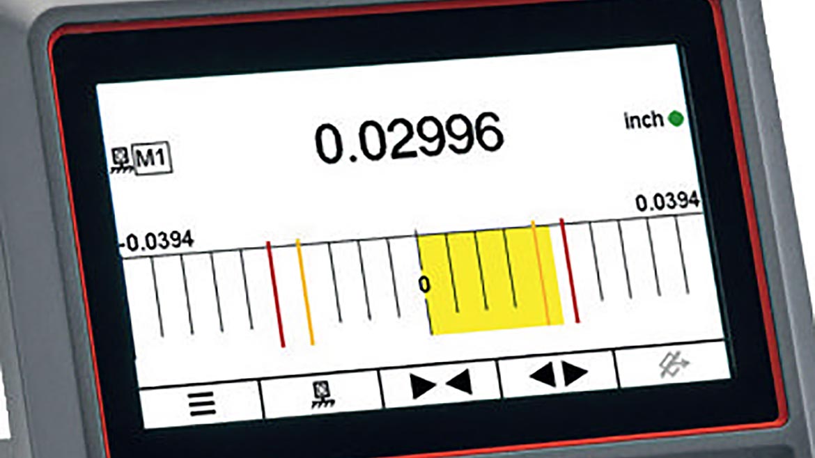
Today, measuring displays are increasingly going digital for many reasons. First, more users require data collection for quality and process monitoring. One can get more powerful measuring systems through digital-dynamic functions, actual part sizes, and automated processing. Also, most analog display systems are based on mechanical or electronic meter movement. Since these meter movements are becoming either costly to manufacture or harder to find, these types of readouts are in the final stage of their product life. Third, digital-based sensors can offer long-range and high resolution in one unit, so it is not necessary to match displays with tooling for proper use. Instead, the tooling measuring range determines the measuring capability and not the display. And finally, digital displays do not have the range/resolution issues of an analog dial; digital readouts provide both long range and high resolution.
Thus, most air tooling is built around designing the best clearance between the air tool and the part based on the tolerance and the size of the part measured to minimize centralization errors, especially for smaller diameters. Therefore, the display will function with long or short-range tooling while presenting a high-resolution digital value.
One of the latest breakthroughs in digital readouts is that the displays are becoming as high resolution as some of the best TVs today with similar refresh rates. In the past, displays have tried to simulate an analog display, but often the results were marginal, with LEDs skipping while trying to keep up with the reading. But with today’s display capabilities, an analog simulation is just as sharp and crisp as an analog meter.
Configuring For Changing Requirements
Many of the air gage readouts that have been available for decades were single-use, dedicated to the tooling systems. This could be a good thing at times because it was simple; users would get used to their operation and easily multiply through the workshop. However, on the downside, if that job requirement disappeared, the display, while still functional, had no use until a similar application came along.
As with the tooling and improvements, changes in performance and added value are also seen in readout systems. With the new and high-volume production of electronics, one can purchase next-generation displays for less cost than mechanical meters being manufactured now. This provides an added incentive to move to digital displays.
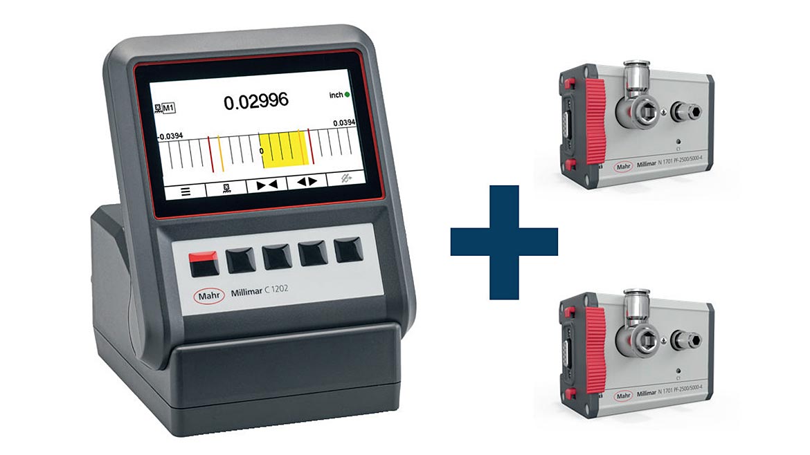
Additionally, digital bench amplifiers for air systems are no longer dedicated to air. Instead, more systems are designed to have a modern, powerful, full-featured display “base unit.” This allows the user to configure the base unit with the type of input needed for the application, whether air, LVDT, or digital probe. As previously noted, since air tooling has not changed much in the past 80 years, it is possible to make significant digital display updates at prices less than the old system may have been purchased for. The value comes from better performance, features that simplify the part classification for the user, and built-in data-sharing capabilities for process monitoring.
However, upgrading is not limited to the same manufacturer tooling. Since we know air tooling works on the same laws of physics, all manufacturers’ tooling is very similar. Therefore, the potential exists to get a readout upgrade for the user. And since these digital systems have much more capabilities, it is simple to move from single- or dual-master step up with the same system, again, based on the similarities of all manufacturers’ tooling.
But another option for these newer modular systems with universal bases is that they can be made an air gage system for one application. Then, if that job goes away, it can be turned into an electronic LVDT-based display by reconfiguration.
Ditch The Readout
Walk around any shop today, and it is not unimaginable that there is a PC at every workstation, along with one, two, or three dedicated bench amplifiers used to make checks on the parts being manufactured. While the standalone bench amplifier is busy qualifying parts, more often than not, the PC may be used for more simple mundane tasks such as emails, a time clock, tracking part and process trends from data, or surfing the web for Amazon bargains.
The point is that there are now options to reconfigure this whole workstation. As with the above, we learned that single interface modules could change a display from air to LVDT input. When connected through a standard USB interface, these same modules can turn that partially used workstation PC into a powerful gaging bench amplifier or intelligent gaging station. Now, instead of having several standalone air gages and LVDT-style bench amplifiers, the gaging computer has the interfaces available to configure all these input types.
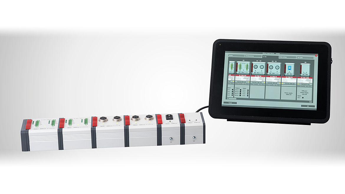
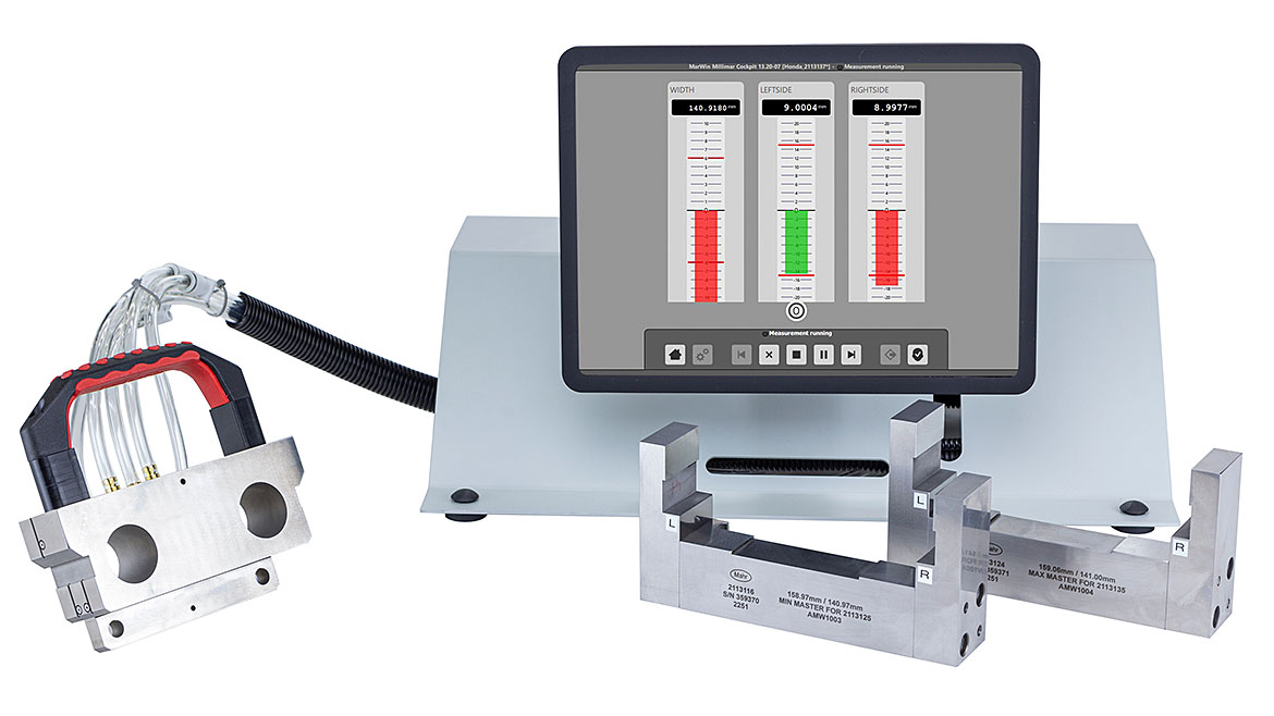
This is where less becomes more for the gaging process. The computer now provides the visual indication for the operator to look at individual displays and watch the changing tolerance colors and the data being acquired. And because the gaging computer is most likely already networked and communicating with other systems, data and measurement results can flow seamlessly within the factory. Thus, the gaging computer has become the display, data collection device, results classifier, and overall guide to the measuring process while in the background, information is being shared transparently with the user.
Once a single workstation is updated with modules taking up less bench space or even none should the module be mounted behind or under, it can be the start of a work department value update. All the old and potentially discontinued displays are replaced as part requirements are changed, input modules can be reconfigured, and since everything is networked, part programs and data can be shared in one central location.
The Air Gaging Isn’t Changing; The Benefits Of It Are
That air tooling you have been using forever has served you well. Whether measuring simple diameters or taking advantage of air tooling measuring geometric conditions at the point of manufacture—taper, concentricity, squareness, or matching parts—you are not apt to find a better solution for tight tolerance inspection requirements.
The advances today will come from longer-wearing tools available faster, information systems that provide higher resolution results in formats, and information more powerful than ever before.
Looking for a reprint of this article?
From high-res PDFs to custom plaques, order your copy today!


