Test & Inspection
How Do Tap Limits Affect Gage Selection?
It is not always as simple as it sounds.

All Images Source: Vermont Gage
One of the more frequent questions we receive is: I am tapping a ¼-20 UNC 2B internal thread with an “H13” tap, what gage do I need to inspect the threaded holes in my parts after tapping? Seems like a plausible question. It should be easy to get an answer from either the tapping or gaging experts… Unfortunately, it is not always as simple as it sounds.
If the threaded hole is a standard diameter and pitch or TPI combination with a standard thread tolerance class, there are a number of readily available technical resources from tap manufacturers, distributors that will assist with this decision. The problem starts when a machine shop receives an order for a thread that may be plated or hardened by heat treating. (Custom or proprietary threads may also cause this issue.) Both plating and heat treat processes will cause changes to the tapped internal product thread. In both cases, an allowance needs to be made at the machining operation prior to the process to insure the threads are in tolerance after plating or heat treat. If we use standard taps and gages, then apply heat treat or plating, the threads will get smaller after the process. In many cases, this shrinking size will cause the product to fail the standard gages for the specified thread size.
Typically, the machinist starts the process by creating sample test parts using various larger tap sizes. They then send the samples out for the plating or heat treat process. When the parts are received from the vendor, the customer inspects the samples to see which parts pass their calibrated Go / No-Go thread plug gage. This then becomes the preferred tap size (GH, H or D limit) to manufacture the threaded hole. They send the thread size and preferred tap limit to the purchasing department / distributor to request a quote for the taps and the gages to inspect product produced by this approved tap limit.
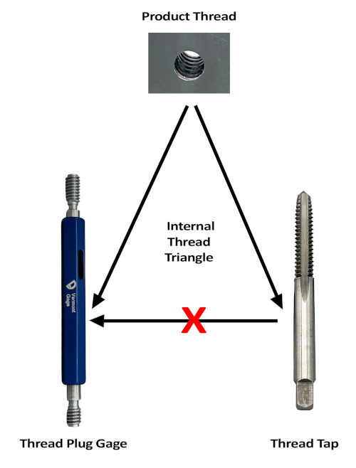
This is where the entire process grinds to a halt. The gage manufacturer is going to ask for either the gage, the product thread Tolerance Class, (i.e. 2B, 3B, 6H, 6G …) or the special min and max product pitch diameters. The distributor or buyer will state the tap limit and be advised that gages cannot be manufactured to the tap limit. As you can imagine this discussion gets a little contentious. This is where the perceived “Internal Thread Triangle” falls apart.
While it is true that the product tolerance dictates both the gage and the cutting tool, the reverse is not true. The gages do not dictate the taps and the taps do not dictate the gages. If we made gages to tap tolerances, the customer would scrap a lot of in-tolerance, good parts. Taps and other cutting tools only generate the internal thread dimensions at a specific zone within the product tolerance.
If the customer decided to use a gage based on the Tap tolerance, typically - 0.0005”, 0.2195” Go / 0.2220” No-Go (Fig. 1), the customer would receive a gage where any two or more operators inspecting the threads could have both the Go and No-Go fit. For this reason, we do not make a Go /No-Go thread plug gage that has a less than 0.0012” separation between the Go and the No-Go pitch diameter. This gage would not be functional and would not give the user a fair pass / fail inspection of the product thread. The other problem is if the customer was able to use the gage, any part smaller than 0.2195” would fail the 0.2195” Go thread plug PD. All product threads in the pitch diameter range of 0.2175” to 0.2194” would be scrap but, according to ASME B1.1, would be in tolerance.
To help us better understand the reasons gages should not be made to tap specifications, let’s take a look at the taps and gages for a standard ¼-20 UNC 2B internal thread. In the (Fig. 1) chart, you will see a graphical example of the various tolerance bands based on the Thread Class for both a Unified Inch Screw Thread and the M Series Metric Screw Thread. The ¼-20 UNC thread data and various Classes are shown on the left. The minimum Pitch Diameter or Basic Pitch Diameter is the starting point for the product, taps and gages. Internal threads are built based on a premise of the Basic PD + the Tolerance Class for both the product and the gage specifications. Taps are designed and have a tolerance based on a deviation above the “Basic” or minimum pitch diameter of the internal product thread. Taps for Unified Inch screw threads have “H” Limits that dictate the pitch diameter of the tap. Each “H” value equals 0.0005” added to the Basic pitch diameter.
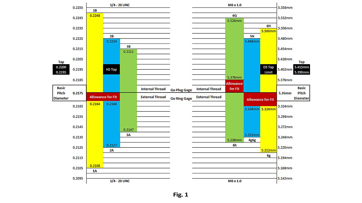
Cutting a ¼-20 UNC 2B internal thread with a Basic PD = 0.2175”,the generally suggested tap “H” limit to create a Class 2B thread is an “H5” tap limit.
Example:
H5 Tap Limit = Basic PD + (0.0005”x 5)
H5 Tap PD = 0.2175” + 0.0025” = 0.2200”
This means that the Tap will create an internal thread pitch diameter of 0.2200” or larger. As you can see the 0.2200” Tap PD is smaller than the maximum product and No-Go plug gage pitch diameter of 0.2224”. In this case there is a 0.0024” clearance below the top of the product pitch diameter tolerance. This clearance will allow for some other machining issues from the tapping operation. The issues may be run-out in the tap, the tapping head or the material being tapped. As long as the internal thread pitch diameter is larger than the “Basic” (minimum) pitch diameter 0.2175”, the GO thread plug gage should pass the full threaded length of the internal thread.
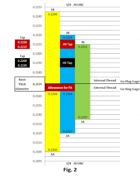
If the product manufacturer decides to use a larger tap to manufacture this thread, they may not need to order a special gage, until the pitch diameter of the tap exceeds the max part and No-Go pitch diameter of 0.2224”. This would roughly equal up to an “H9” tap limit at a pitch diameter of, 0.2175” + (0.0005” x 9) = 0.2220”, (Fig. 2). When the special oversize thread causes the manufacturer to use a tap pitch diameter larger than the maximum product pitch diameter is when things get more challenging.
In cases where the customer is applying plating to the thread, both the ASME B1.1 and the ASME B1.13M product thread standards have calculations for Pre-Plate thread adjustments. This math works well for flash or other light plating. If heavy plating is applied, these formulas will generate pitch diameters where the Go Pitch Diameter is calculated larger than the No-Go Pitch Diameter. This creates a non-functional gage that will generate 100% scrap, if used. Any internal thread that accepts the Go gage will accept the smaller No-Go gage.
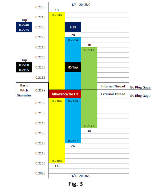
Fig. 3 shows a thread that is using an “H13” tap. This is when “H” limit tap sampling is required by the product thread manufacturer. The sampling to select the tap “H” limit is only the first step. The next step is to develop what the product pre-heat treat or pre-plate minimum and maximum pitch diameters will need to be. There are no quick or simple calculations that will generate the required min and max product pitch diameters for taps that cut threads larger than the standard max pitch diameter. Some customers elect to only buy a special No-Go thread plug that is a little larger than the max pitch diameter of the tap. Others will add the worst case tap run-out deviation to the max tap pitch diameter and use this as the new special No-Go. If they choose to inspect the minimum pitch diameter of the oversize thread, some will subtract the standard PD tolerance from the newly calculated oversize Max PD. This is then used as the custom Go gage and product PD before plating.
Example:
¼-20 UNC 2B preferred tap = H13 tap limit
H13 = 0.2175” + (0.0005” x 13) = 0.2240” tap pitch diameter.
Manufacturer calculated tap run-out = 0.001”
No-Go thread plug gage PD = 0.2240” + 0.001”
= 0.2250”
Go thread plug gage PD = 0.2250” – (0.2224” – 0.2175”)
= 0.2250” – 0.0049”
= 0.2201”
The above example and other options described for Oversize Taps are only examples of what may be done to help the customer to create a minimum and maximum pitch diameter. There may be other calculations and variations based on the specific industry standards, company or engineering developed calculations, materials being tapped or testing to create the required min and max pitch diameters.
Note: The general reference material stated here for taps is based on my experience only. I am not a tap expert. Your tap manufacturer is the expert and may have other tools or suggestions.
Anytime a gage customer only supplies a Tap Limit, i.e. H, GH or (D for metric taps), and does not supply the Thread Tolerance Class or Pitch Diameters, the gage manufacturer is going to ask for the Thread Tolerance Class or the Min and Max Pitch Diameters. The product thread specifications drive the selection of both the gages and the cutting tools. Unfortunately, the tap alone is not enough to accurately order gages to inspect the product threads.
Looking for a reprint of this article?
From high-res PDFs to custom plaques, order your copy today!


