The Gage Selection Conundrum
The correct selection of measuring devices will ensure the quality, price and delivery of the products we manufacture and use.
The goal is to ensure we have the correct inspection tools to ensure the quality of the product produced.
Selecting gages and other types of measuring tools can be challenging. It does not matter if you are an experienced or novice gage user, tool crib manager, lab manager or buyer. In some cases, these decisions can have detrimental effects on the finished product. In others, the gage cost and calibration frequency adversely influence the final cost or delivery of the product. These concerns and others must be considered prior to selecting, quoting or ordering any type of measuring device.
There are guides and rules that may be applied to make these decisions easier, more accurate, quicker and less expensive. The goal is to ensure we have the correct inspection tools to ensure the quality of the product produced. The decisions should be the same regardless if this is a new part or one that has been manufactured for years.
The new or prototype part requires the development of some type of measurement plan. This plan contains all of the reference information for the measurements, industry or company standards and the applicable selected decision rules. It may be as simple as a list of all of the features to be measured and the tolerances of those features. A more detailed plan may be required based on the complexity of the part or the industry being served. In this case, knowledge and use of ASME B89.7.2 “Dimensional Measurement Planning” will be beneficial. Once the decision rules have been created, the search for the best measurement options may begin.
A legacy part that has been manufactured for years may already have a measurement plan in place. This plan should be reviewed on some type of cycle. Legacy parts have their own unique challenges. Measuring devices or techniques may have changed. The chosen measuring tools may no longer be available. The original designers, engineers, and quality assurance people may have changed. Those that replace them inherit the previous team’s decisions. Over time, some information or reasons for the decisions may be lost. When it is asked why a tolerance or decision has been made, the answer is: “This is how we have always done it.” The information that is passed from predecessor to current manager/user tends to lose some important information or reason for the decision. Some form of measurement plan will help to eliminate this problem. It will also give us a baseline for our measurements. If a mistake is made or an update is needed, the plan may be corrected or updated.
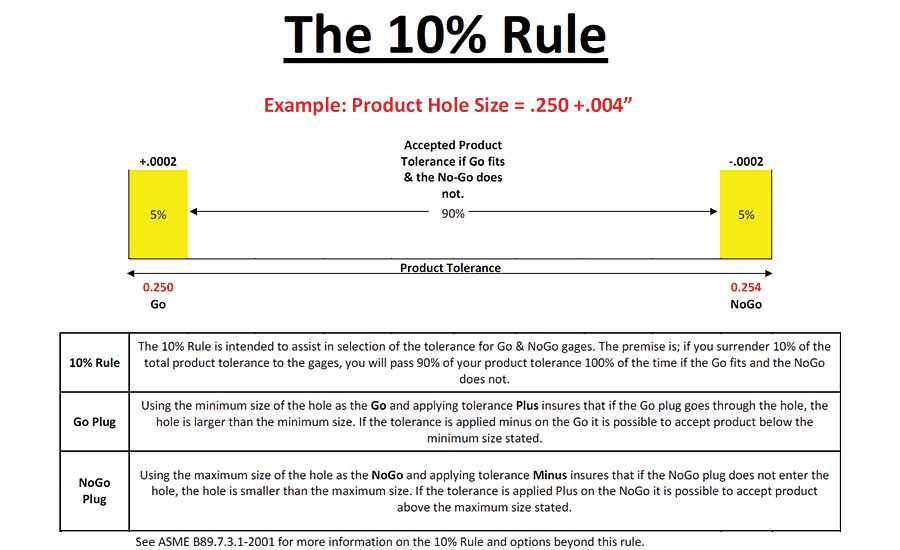
Figure 1. In this example, the product tolerance is .004”.
Within the measurement plan are decision rules. These decision rules help us to select the best measurement tool based on the product design, material, industry standard, dimensions and tolerances. The product tolerances dictate the gage tolerances. The gages never dictate the product tolerances. The gages and measuring tools must have an accuracy that is less than the product tolerance by some factor. Guard bands represent these factors. The guard bands protect the extremes of the product tolerance. In the example in Figure 1, the internal diameter is .250” - .254” (.250 +.004”).
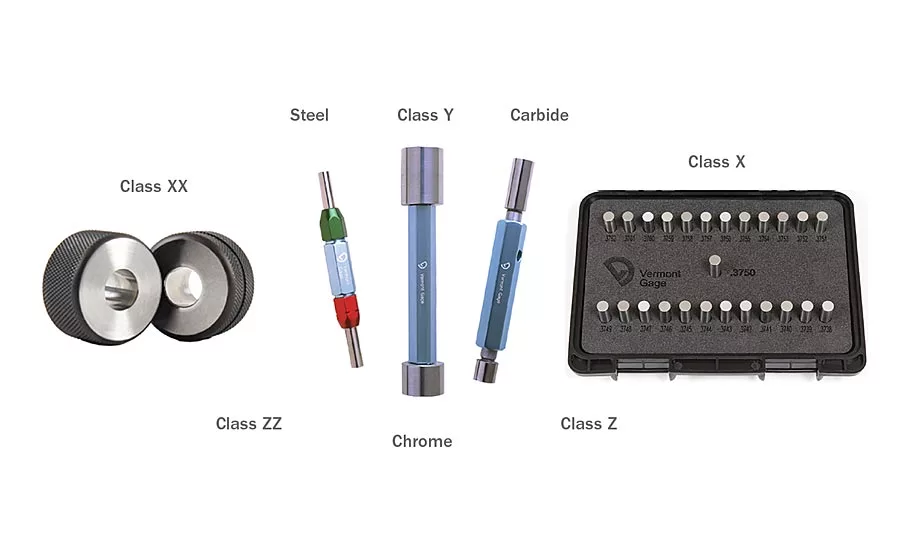
Using the 10% Rule as our guide or starting point, the decision rule is binary; only two possible outcomes: pass or fail. Binary rules are typical for go / no-go fixed limit gages. In the Figure 1 example, the product tolerance is .004”. The calculation (.004 x 10% = .0004”), the total tolerance the gages may use is .0004”. This tolerance is split (.0004” / 2 = .0002”). One half applied to the min and max product diameters. The suggested gage tolerance would be .0002”. This equates to a Class ZZ gage tolerance per ASME B89.1.5 (Fig. 2) for this diameter range. The suggested gage would be .2500” + / .2540” – Class ZZ go / no-go plug gage assembly. This example works for suggesting a fixed limit plug gage.
Let us assume the part has an internal diameter of 4.780” +.040” tolerance (4.780” / 4.820”). In this case, you could use a 4.780” / 4.820” Class ZZ Trilock go / no-go plug assembly. You could also use and ID micrometer or a bore gage that has a 10:1 or better accuracy (+/- .002” accuracy). The decision comes down to a couple of factors. If you need an actual measured value, a variable gage would be the best choice. (As long as the variable gage meets our +/-.002” accuracy.) If pass / fail is all that is required, the go / no-go plug gage will work. Cost and availability are also considerations. There are a number of other questions to consider. If the gage we have in house has the required accuracy, is available and recently calibrated, we use the in-house gage.
Parts with a tighter tolerance can be more challenging. Using the example of a part with .250” +.0005” internal diameter, the guard band (gage tolerance) calculation and the inspection become more difficult. Using the 10% Rule, the product tolerance is .0005”. Ten percent of the product tolerance is .000050”. The binary min and max tolerance = .000025”. Using 10:1 a .2500” + / .2505” - Class XX (.000020”) go / no-go plug gage would be used to inspect this internal diameter. How frequently will we have to calibrate / replace the go gage? Should the go gage be carbide to prevent wear? Do we need to use the 10:1 rule or should we use 4:1 or some other ratio? Many of these decisions come down the accuracy of the measuring device and the amount of the product tolerance we can surrender to the measuring tools and the material of the product inspected. (The 4:1 rule usually comes into play in lab environments for the calibration of the measuring tools.)
If surrendering 25% (4:1) or 10% (10:1) of the product tolerance to the measuring device is not practical, the use of incremental plug gages, or a combination of both fixed limit and variable gages may be used. In the previous example, we could use three Class X Go pin gages to creep up to the minimum internal diameter size and the calculated no-go gage. The three go plug gages could be .2498”, .2499” and .2500”. All three gages would have a +.000040” tolerance. This allows us to account for some of the allowance for fit between the gage and the part. This will not give us an exact value for the low side of the hole. It does reduce the possible variations. If the .2498” & .2499” both fit and the .2500” does not or is snug, it would indicate the hole is between the .2499 and the .2500 diameters. Force, surface finish and part geometry will affect the accuracy of this option. (Never force a gage.) In measuring shafts, many customers will use a fixed limit go ring gage to represent the max material condition and hand micrometers to check for min material condition.

Figure 2. The suggested gage tolerance would be .0002”. This equates to a Class ZZ gage tolerance per ASME B89.1.5 for this diameter range.
All of the rules mentioned here are starting points. They are the beginning of the decision making process. The ASME B89.7.3.1 “Guidelines for Decision Rules: Considering Measurement Uncertainty in Determining Conformance to Specifications” will assist with taking these decision rules to the next step. This standard also offers suggestions and examples for dealing with measurement disputes and other product driven decision rules. The correct selection of measuring devices based on the product designs, materials, dimensions and tolerances of the product will ensure the quality, price and delivery of the products we manufacture and use.
Looking for a reprint of this article?
From high-res PDFs to custom plaques, order your copy today!


